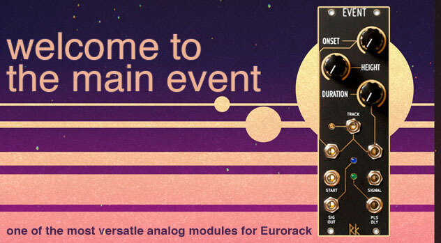

VCO, envelope, slew limiter (portamento), waveshaper, LFO, envelope follower… The EVENT does it all, making it one of the most versatile analog modules available.
Controls:
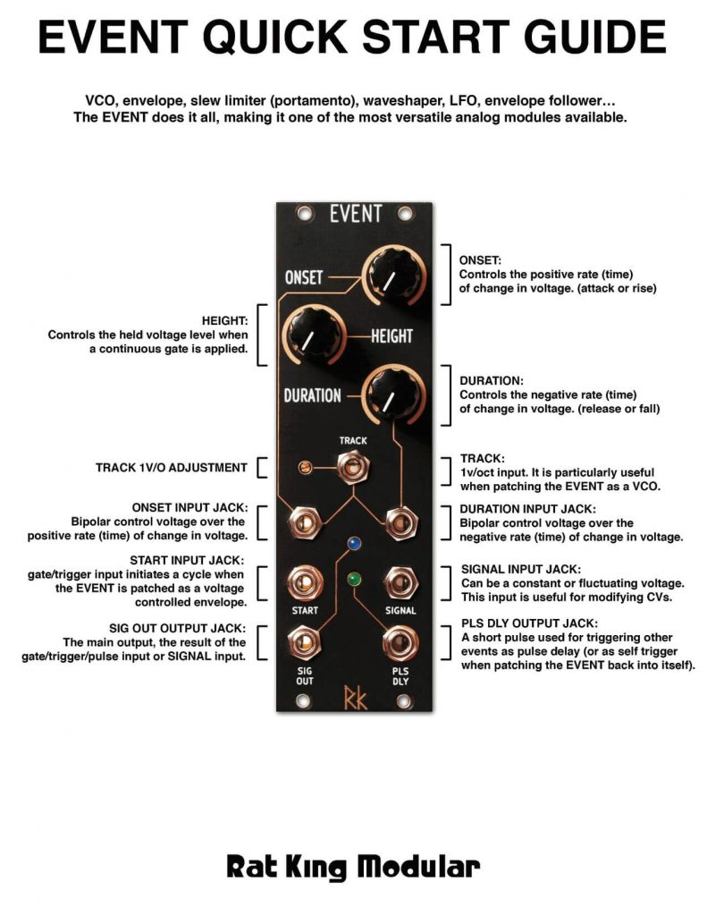
- ONSET: Controls the positive rate (time) of change in voltage. It has a bipolar CV input jack.
- DURATION: Controls the negative rate (time) of change in voltage. It has a bipolar CV input jack.
- HEIGHT: Controls the held voltage level when a continuous gate is applied.
- TRACK: 1v/oct input. It is particularly useful when patching the EVENT as a VCO.
- START: A simple gate/trigger/pulse input that initiates a cycle when the EVENT is patched as a voltage controlled envelope.
- SIGNAL input: Can be a constant or fluctuating voltage. This input is particularly useful for mangling CVs.
- SIG OUT: The main output, the result of the gate/trigger/pulse input or SIGNAL input.
- PLS DLY: A short pulse used for triggering other events as pulse delay (or as self trigger when patching the EVENT back into itself).
Specifications:
- Module width: 8HP
- Module depth: 22mm
- Current draw:
- +12V:
- -12V:
View the assembly instructions here.
View the bill of materials here.
Patch suggestions
Envelope:
Patch a gate or trigger output to the start input. Patch the output to any CV input. Change the position of the ONSET, HEIGHT, and DURATION knobs to create a corresponding change in the shape of the output CV. Keep in mind that the time required for ONSET and DURATION to reach their maximum value is from practically 0 to essentially infinite! You may think this is a problem, but this ridiculous range is useful when the EVENT is made to perform as a VCO (described below).HEIGHT controls the voltage level when a gate is held. One could say it is a “sustain” control, if that is the kind of terminology you prefer.
ONSET and DURATION can each be controlled in two ways. Obviously the knob control determines stage length, but there is also a CV input each for ONSET and DURATION. Additionally, there is another CV input (TRACK) which controls both ONSET and DURATION inversely. (I know, it’s confusing, but we’ll get there. The complexity is what makes it so useful!) A positive change in CV input on either of the ONSET or DURATION inputs will cause an increase in the time of that stage. Correspondingly, a negative change will decrease the time. Now, let’s talk about that inverse TRACK input. TRACK is a 1v/oct input (that can be calibrated somewhat to obtain at least 3 octaves of accurate tuning) that is inverse to the individual CV inputs of ONSET and DURATION. This means that an increase in positive voltage will create a decrease in the time of both ONSET and DURATION. This is useful when we want to use the EVENT as a signal source. In other words, a VCO.
VCO:
To turn the EVENT into a VCO there are two things that must be in place. First, take a stacking patch cable and plug in one end to the START input, take the other end and put it into the PLS DLY output. This creates a loop in the circuit. When the EVENT output has reached the end of the cycle (the end of the DURATION stage) a quick pulse is generated. This pulse can be used to recycle the entire output shape. We now have a variable waveshape VCO, but we have to initiate the cycle the first time. This where the need for the stacking cable comes in a trigger, gate, or pulse on either end will start the cycling process (you can also patch a trigger into the SIGNAL jack if you do not have stacking cables). Be careful not to ground the tip of the connector if you unplug it from your trigger source, this will stop the cycle. The output is now a continuous oscillation, the frequency of which is determined by the ONSET and DURATION controls, the CV inputs, and the TRACK input. The curious thing about this VCO is that the shape of the output waveform changes depending on the setting of the ONSET and DURATION controls and the modulation of their inputs. Just as before these controls vary the shape of the output by changing the time it takes to to reach either the peak or trough of the waveform. So, as these controls are varied, either by the knob or CV, the wave shape changes. Possible wave shapes are ramp to triangle to sawtooth, or high harmonic content to low harmonic content (there is another way this can useful when applying a signal source or CV to the signal input). The Track input proportionately changes the time for both ONSET and DURATION and does not change the shape of the output as the voltage is applied proportionally.
SLEW:
A third method of using the EVENT is as a voltage controlled lag processor whose fluctuations in voltage can be slewed in positive change, negative change, or both. In much the same way as the other two patching methods changes are made through knob control or CV input voltages. When using this method of patching the voltage to be mangled should be applied to the SIGNAL input.
Within the description and patching examples we have outlined here there is enough to get you started on thinking about how this module can be used. The EVENT has been named accordingly. By itself, multiple iterations of this one module can perform every basic function of synthesis. Every detail is not laid out here. Part of the magic of modular synthesis is discovery, so go play!