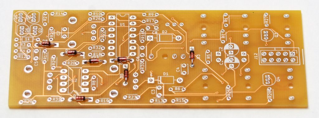
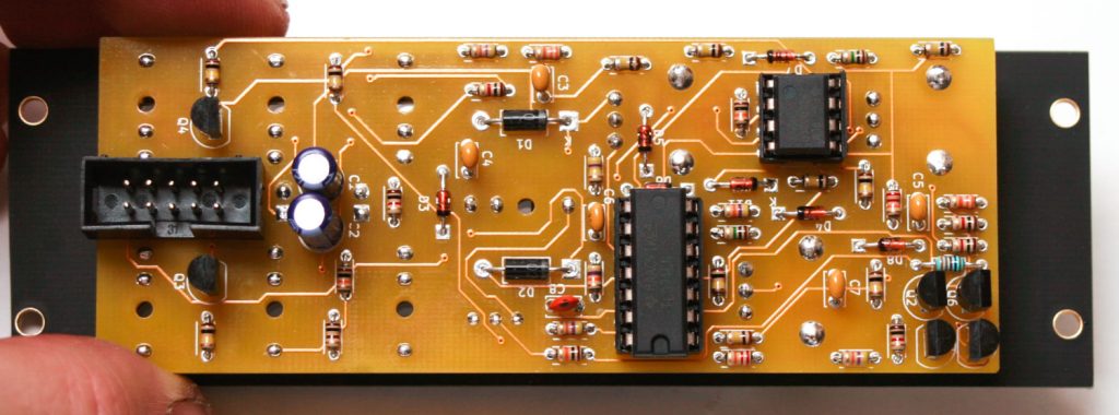
PLEASE NOTE: The newest version of the EVENT PCB has most of the components on one side of the board, rather than having them interspersed on opposite sides of the board as shown in the assembly instructions photos below. Regardless of the version you have, please place the components where the silkscreen indicates they should go.
Thank you for choosing Rat King Modular! We want to give you the best step-by-step instructions as possible to assist you in a successful build. Please make sure to follow these instructions in order and take your time! If you have limited experience please try and get some experience/help before attempting something that you are uncomfortable with. With that said, let’s begin!
Here is a link to the bill of materials with Mouser part numbers.
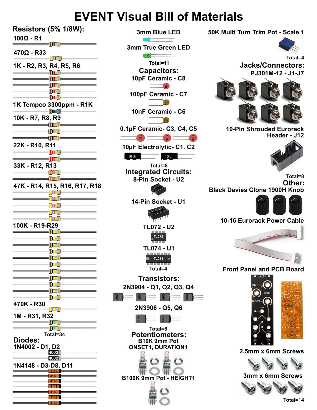
Here is a visual bill of materials. Please note that there is no R33 in V1 of the Event.
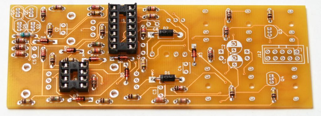
1N4148 Diodes
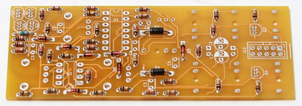
Take the PCB and start by populating the diodes. Diodes are polarized components and have to be oriented properly! Make sure to align the cathode stripe on the diode with the cathode marking on the silkscreen.
Once you have inserted the diodes in place, carefully turn the board over (you can use another PCB or piece of cardboard to hold the parts on) and solder then clip the excess leads.
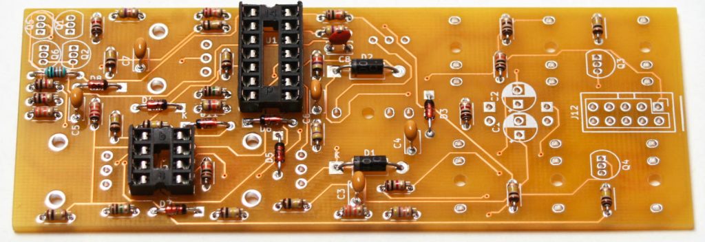
Resistors & Large Diodes
Next up are the resistors which are not polarized so it doesn’t matter which way they are placed in, but it makes troubleshooting a lot easier if you line up all of the tolerance bands (usually a gold stripe) on the same side. Insert each resistor, matching the value to the proper spot as per the BOM.
After that, you can put the 4002 diodes, which are polarized as well.
You can again turn the project over to solder and then clip the excess leads.
IC Sockets
Place the IC sockets and make sure that you align the notch in the IC socket with the notch in the PCB silk screen.
Turn the project over and solder in place.
Ceramic Capacitors
Populate the ceramic capacitors next. These capacitors are not polarized so they can be inserted in either direction.
Turn over to solder then clip excess leads
Power Header and Transistors
First populate the 10-Pin Eurorack power header as shown below. The header’s keyed notch aligns with the silk screen notch. This is very important, please do this correctly.
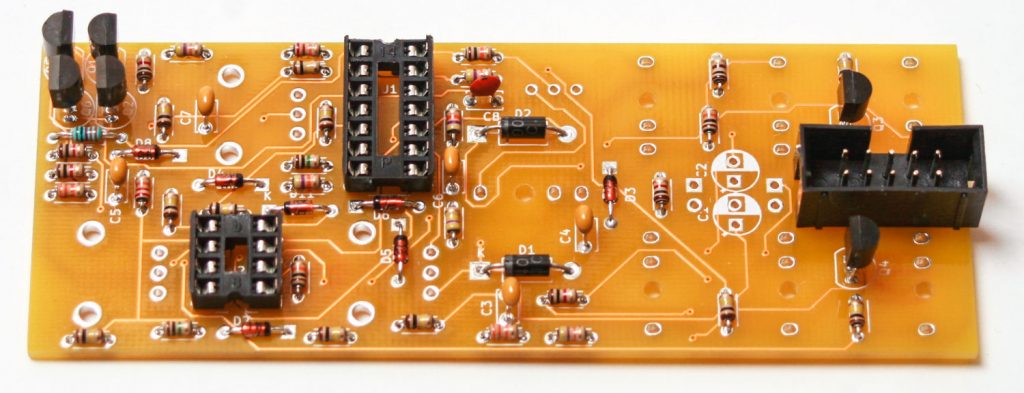
Turn over to solder in place. Next populate the transistors by aligning the flat part of the transistor with the flat side of the silk screen. Turn over and CAREFULLY solder in place. The pad spacing for the transistors is very close together. Be careful to not use too much solder, you might bridge the pads!
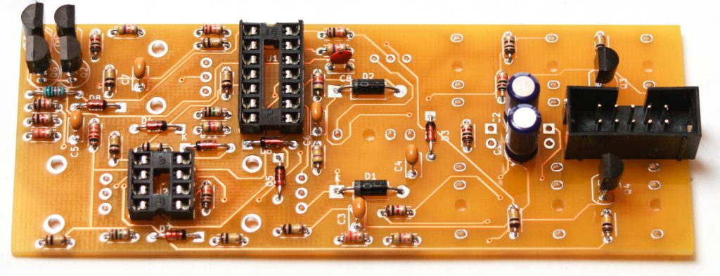
Electrolytic Capacitors
Next populate the electrolytic capacitors. Electrolytic capacitors are polarized, so make sure when you are placing it that you get the longer leg in the square hole, which is closer to the + symbol. Once inserted, turn your project over, solder and clip any excess leads.
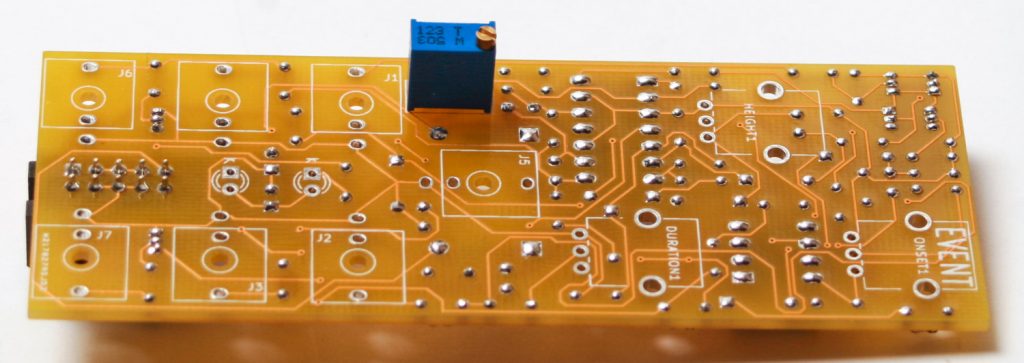
Trim Potentiometer
Turn over to solder and trim excess leads
Now place the multi-turn potentiometer in place as shown below. Make sure you do this exactly as shown the photo so that the trim screw will land behind the panel.
Turn over, solder and trim
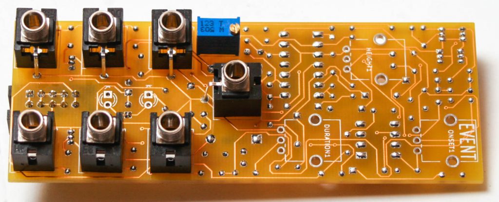
Jacks
Now place the 3.5mm jacks into the PCB as shown below. Carefully turn over and solder in place.
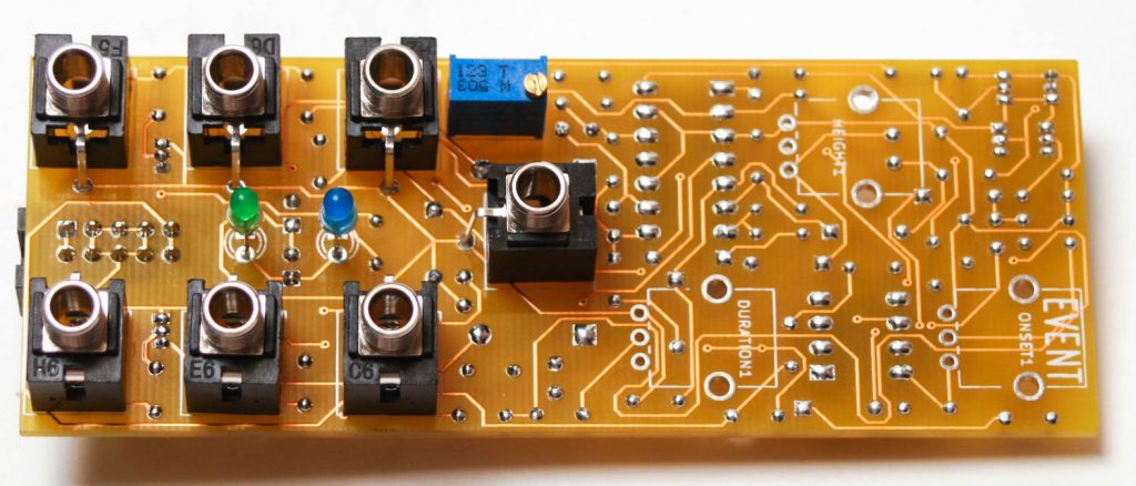
LEDs
Insert the LEDs so that the SHORT LEADs are placed in the SQUARE Hole. This is very important as LEDs are polarized components. DO NOT SOLDER JUST YET! It helps to shove the LEDs up into the panel to prior to soldering!
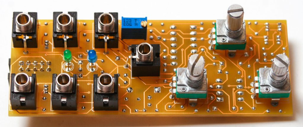
Potentiometers
Add the potentiometers into the PCB, then place the panel onto the project PRIOR to soldering them in place.
Panel Assembly
Place the panel over the PCB components and then hand-tighten the nuts around the pots and the jacks. NOW TURN OVER TO Solder the LEDS in place after you have pushed them forward into the panel.
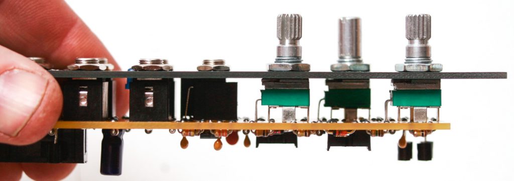
Make sure the jacks and pots are secured into the PCB and panel then solder in place.
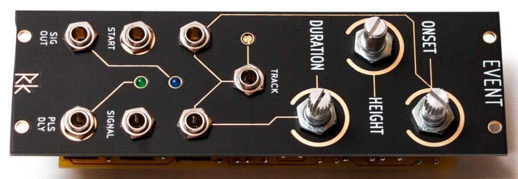
Final Assembly
Finally add the knobs to the pots, gently tighten them in place with a small flathead and get ready to test!