Thank you for choosing Rat King Modular! We want to give you the best step-by-step instructions as possible to assist you in a successful build. Please make sure to follow these instructions in order and take your time! If you have limited experience please try and get some experience/help before attempting something that you are uncomfortable with. With that said, let’s begin!
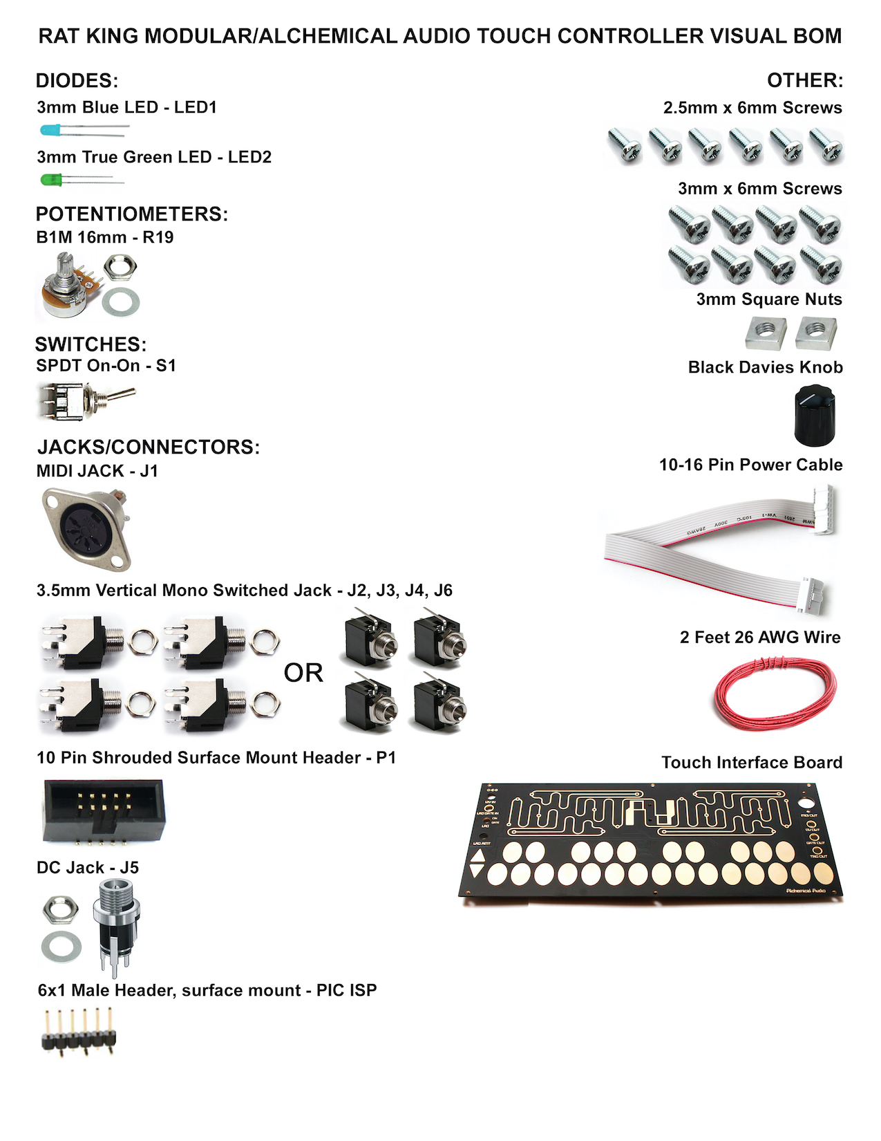
Here is the bill of materials:
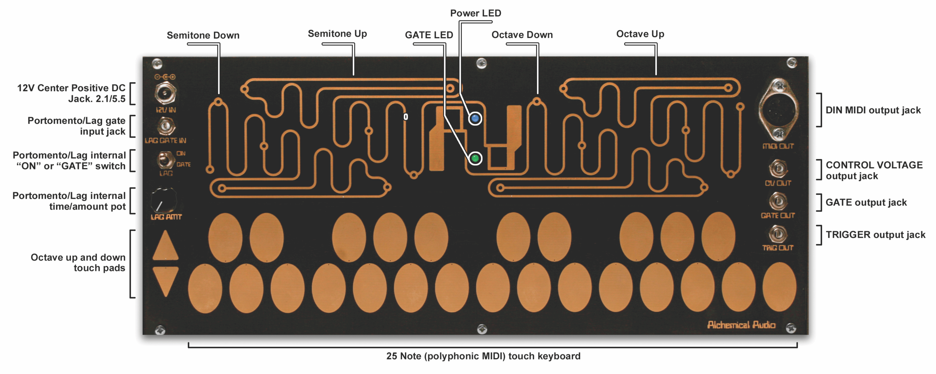
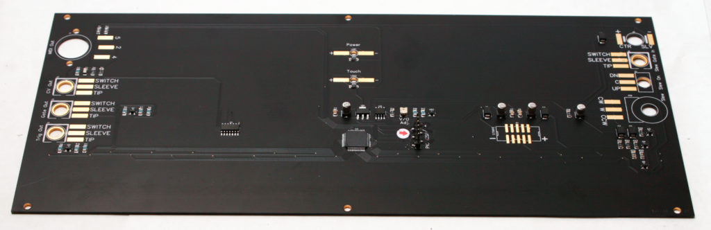
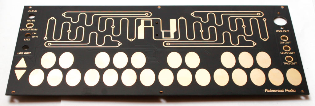
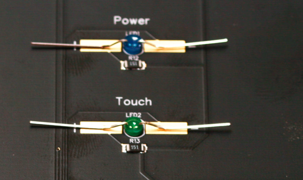
Take a look at the partially completed PCB/Controller Panel:
TOUCH CONTROLLER LEDs
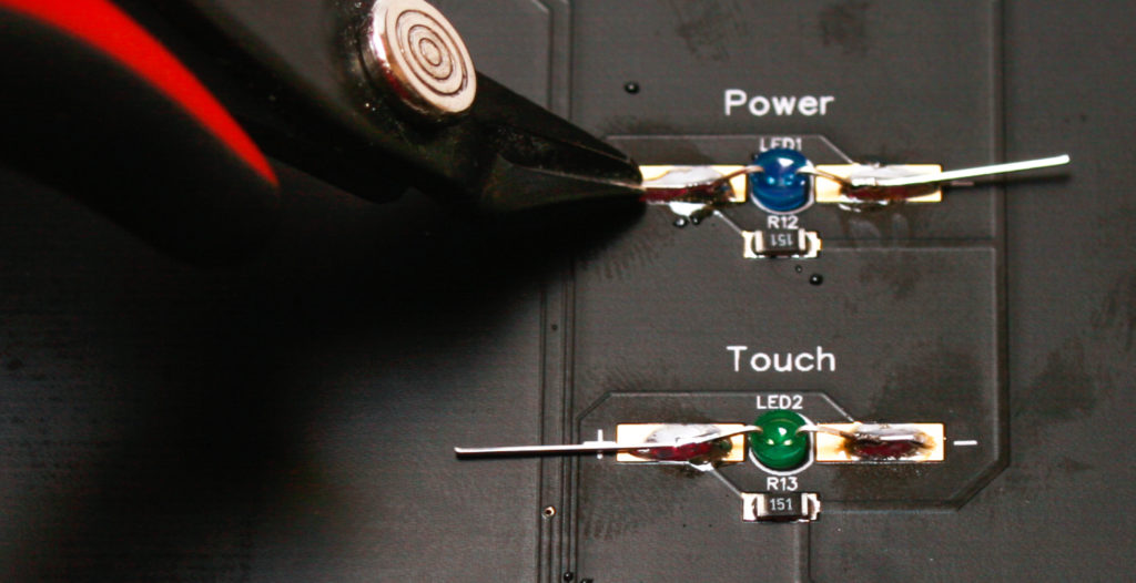
Take your LEDs and bend them as shown below. Make sure that the cathode (shorter leg) of each LED is oriented with the negative pad marked with the “-“. You can now proceed to solder the LEDs in place.
Carefully clip the excess leads.
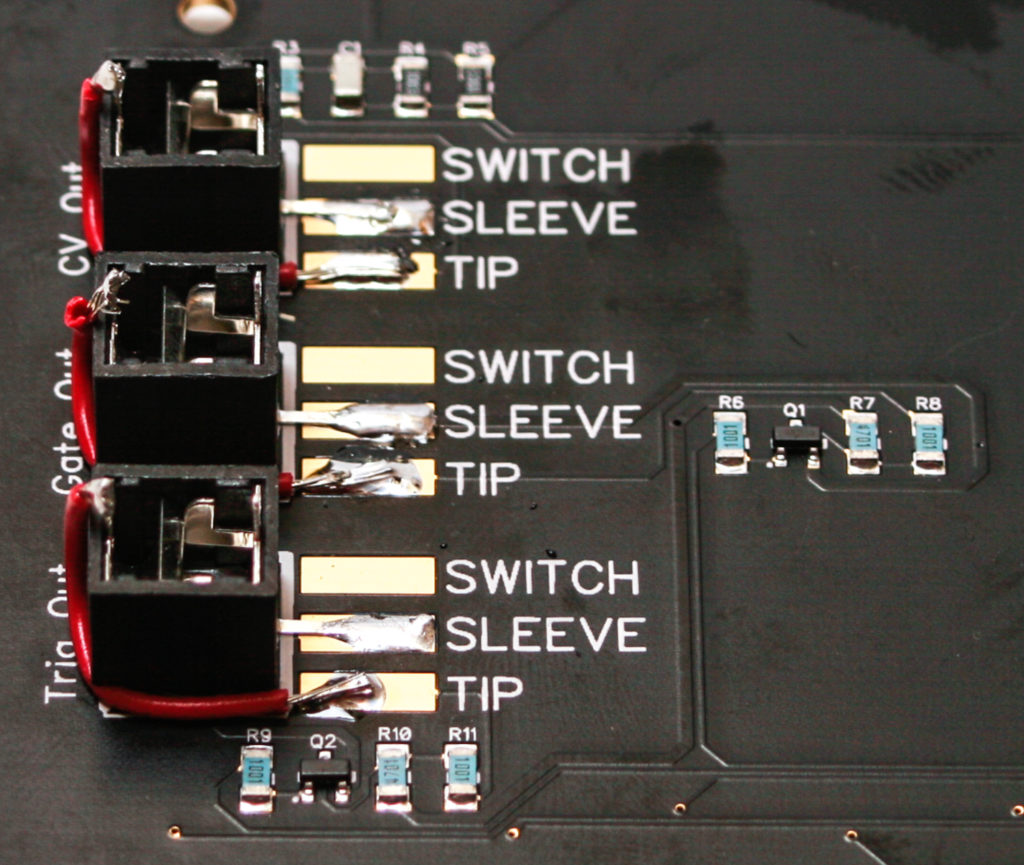
3.5mm Jacks
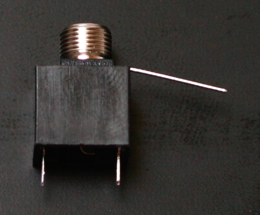
You can use PJ301M-12 (“Thonkiconn”) or PJ301BM (“Erthenvar”) jacks with this circuit. Both style of jacks are shown below.
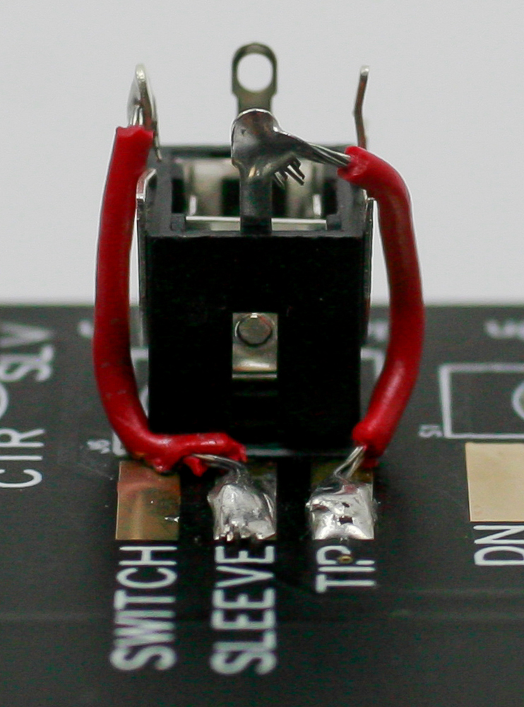
PJ301M-12:
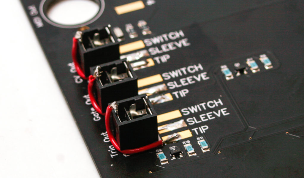
Flare out the 3.5mm jack lead as shown below on all four 3.5mm jacks.
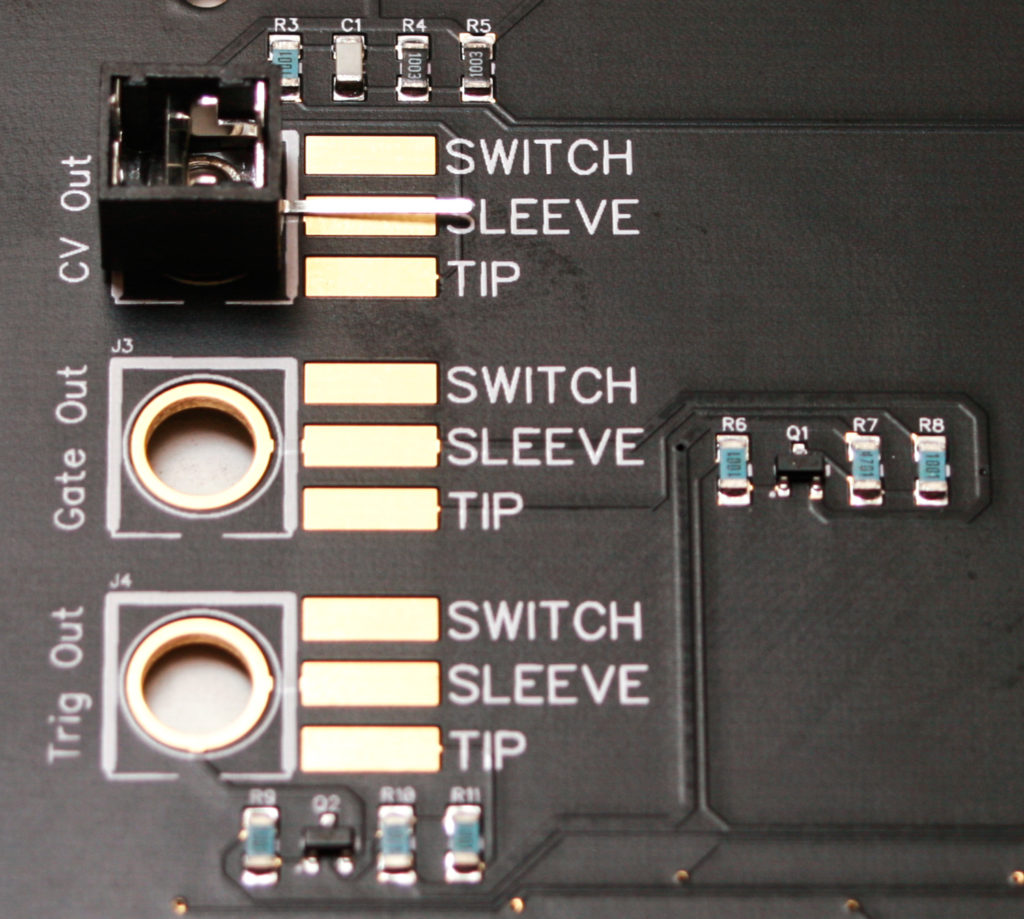
Now place the 3.5mm jacks into the board as shown below.
Turn the project over and gently tighten down the nuts on all four jacks.
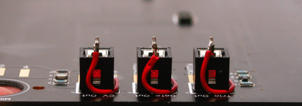
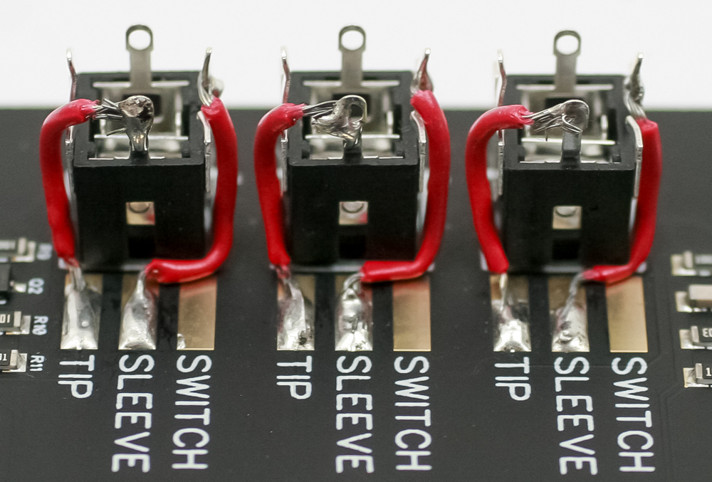
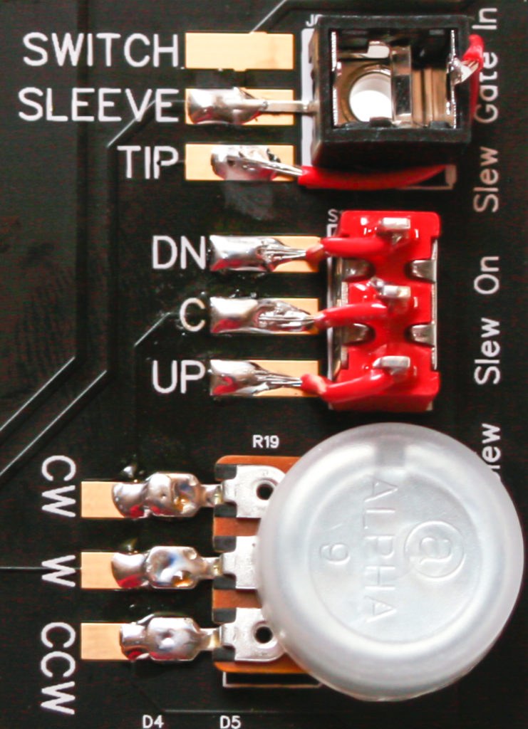
Now solder both the bent SLEEVE pin onto the board and the TIP pin onto the PCB. The TIP pin will require some of the provided wire in order to install.
PJ301BM:
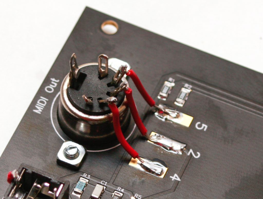
DIN MIDI Jack
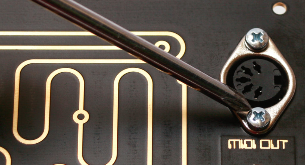
Insert the DIN MIDI jack into the PCB as shown below and secure it with two 3mm screws and 3mm square nuts.
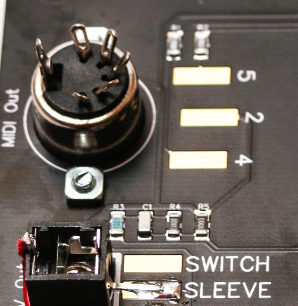
Solder the DIN MIDI pins to the PCB via the provided wire as shown below.
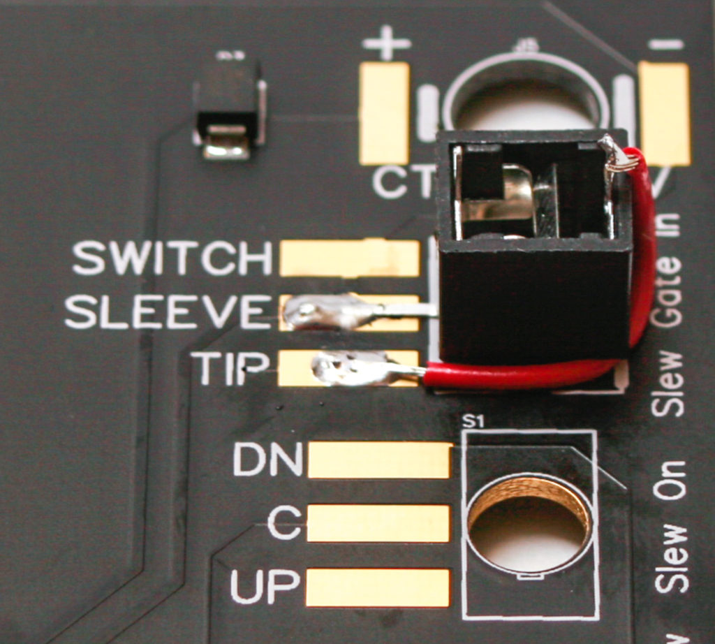
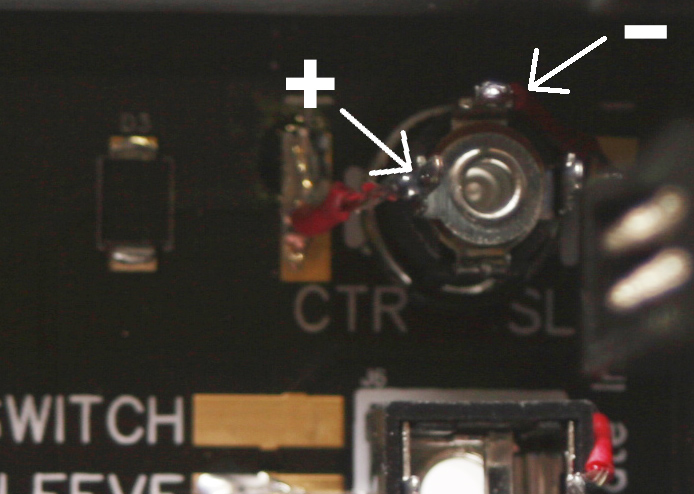
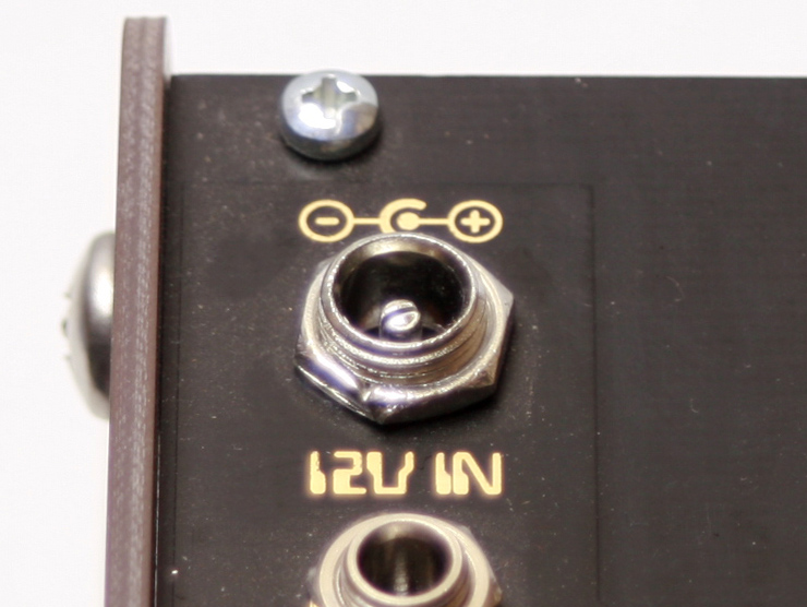
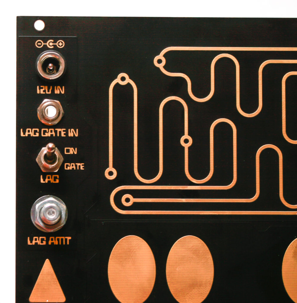
POWER JACK
Now solder the DC power jack to the PCB with the provided wire as shown below. Start by finger-tightening the DC Jack Nut. Rotate the jack before soldering then finally tighten the nut
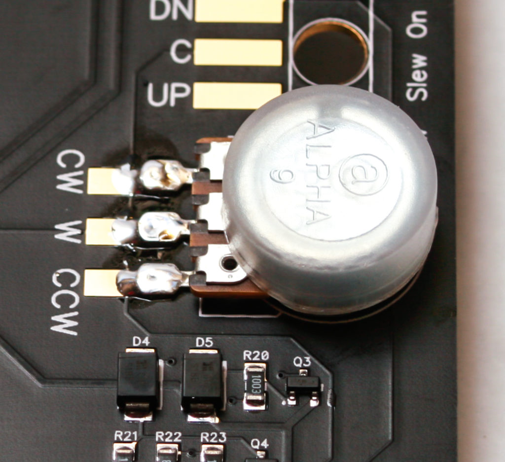
POTENTIOMETER
Now gently tighten down the potentiometer nut.
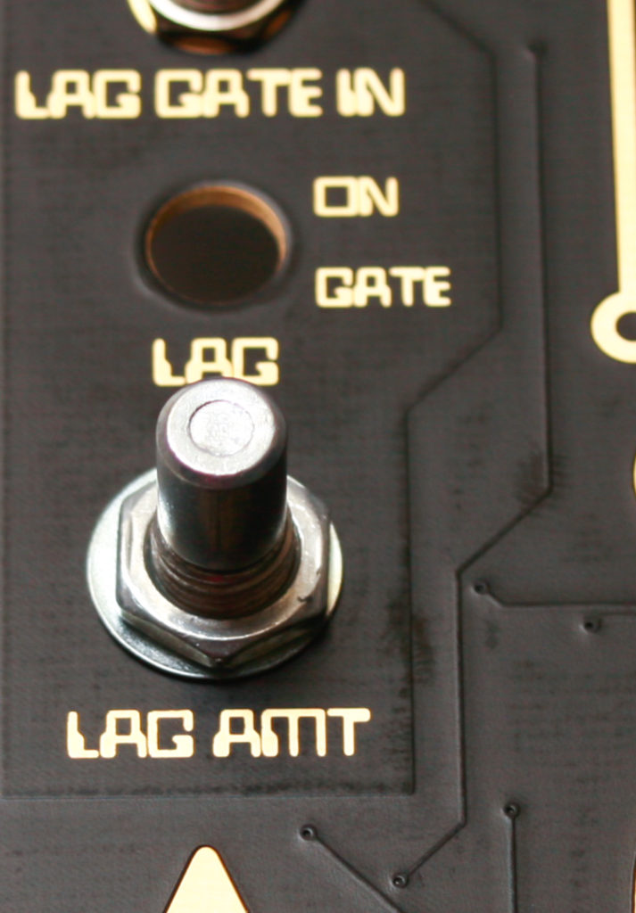
Now take the potentiometer and solder it into place as shown below.
SWITCH
Insert the switch into the board, tightening the nut on top (orientation on this switch does not matter).
Solder it in with wire as shown below.
VOLTAGE OUTPUT TRACKING ADJUSTMENT
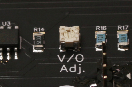
Calibration steps:
- Connect a volt meter (switched to DC) to a patch cable coming from the CV OUT jack.
- Power the unit off, then power it back on.
- When you touch the highest note on the keyboard (C), the Touch Controller will output C5, or 4V.
- Adjust the V/O trimmer (on the back of the unit) with a fine-tip screwdriver until your volt meter reads exactly 4V.
You’re done! Make some music!