Thank you for choosing Rat King Modular! We want to give you the best step-by-step instructions as possible to assist you in a successful build. Please make sure to follow these instructions in order and take your time! If you have limited experience please try and get some experience/help before attempting something that you are uncomfortable with. With that said, let’s begin!
Here is a link to the bill of materials with Mouser part numbers.
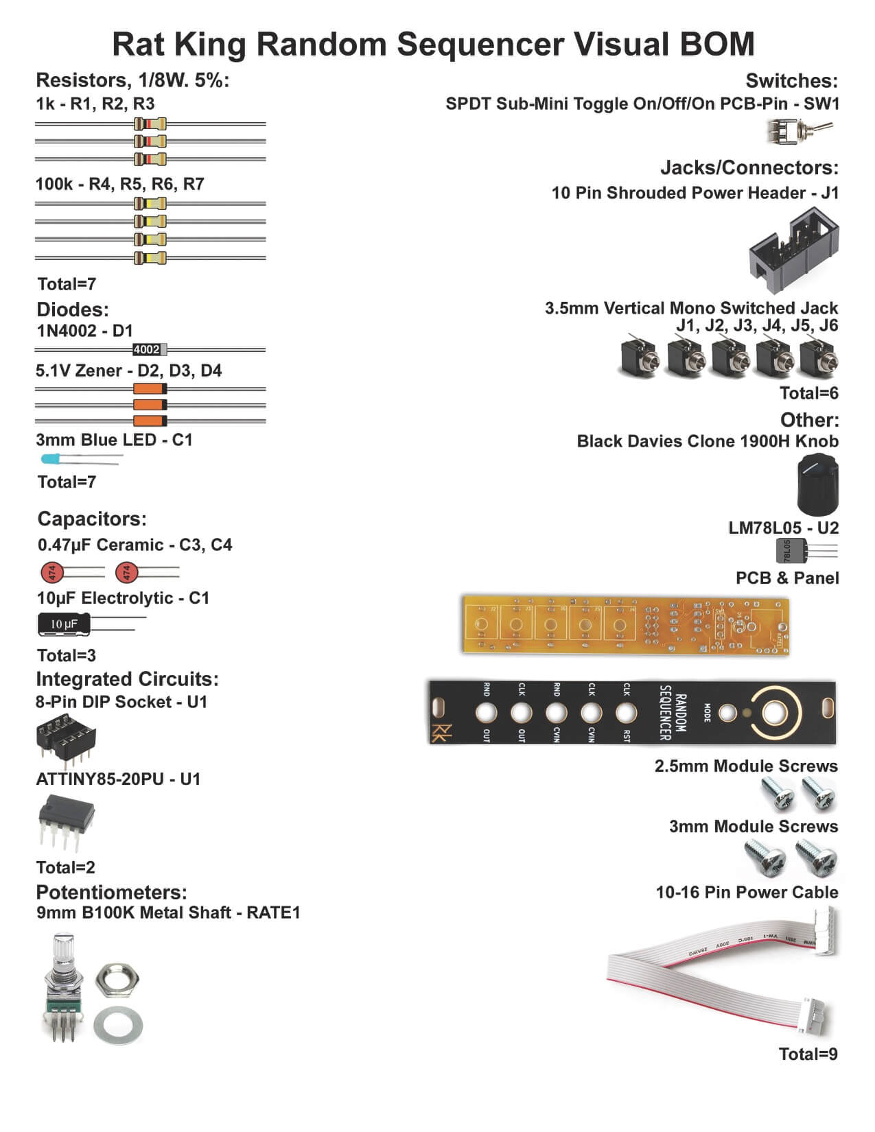
RESISTORS
Resistors which are not polarized so it doesn’t matter which way they are placed in, but it makes troubleshooting a lot easier if you line up all of the tolerance bands (usually a gold stripe) on the same side. Insert each resistor, matching the value to the proper spot as per the BOM
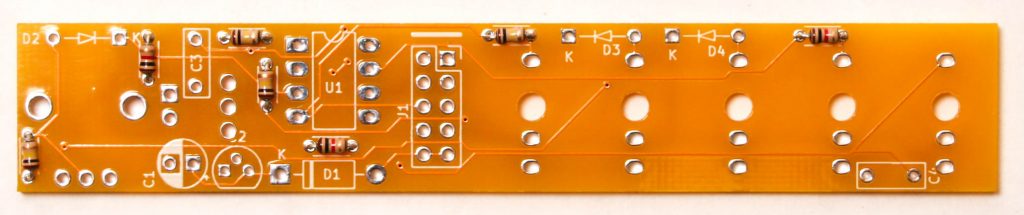
DIODES
Start populating the diodes. Diodes are polarized components and have to be oriented properly! Make sure to align the cathode stripe on the diode with the cathode marking on the silkscreen.
Once you have inserted the diodes in place, carefully turn the board over (you can use another PCB or piece of cardboard to hold the parts on) and solder then clip the excess leads.
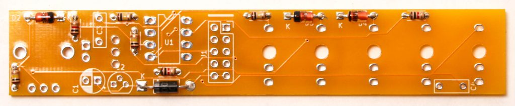
CERAMIC CAPACITORS
Populate the ceramic capacitors next. These capacitors are not polarized so they can be inserted in either direction.
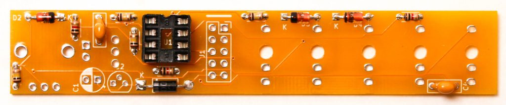
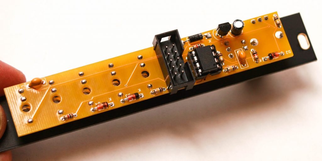
IC SOCKET
Next place the IC socket and make sure that you align the notch in the IC socket with the notch in the PCB silk screen.
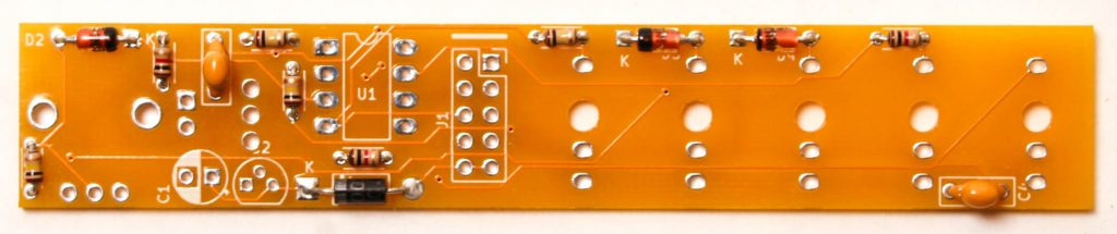
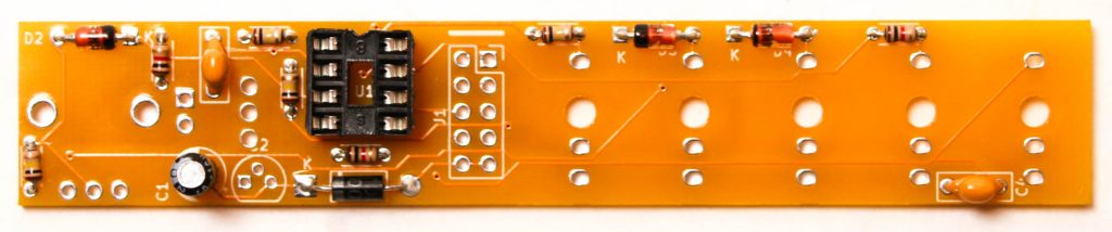
ELECTROLYTIC CAPACITOR
Next populate the electrolytic capacitor. Electrolytic capacitors are polarized, so make sure when you are placing it that you get the longer leg in the square hole, which is closer to the + symbol. Once inserted, turn your project over, solder and clip any excess leads.
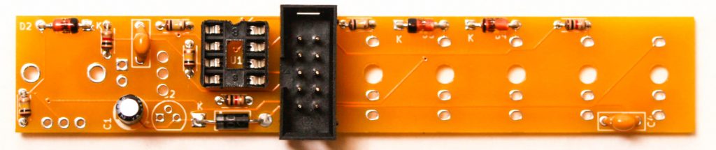
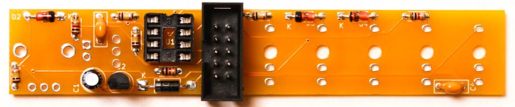
10 PIN POWER CONNECTOR
Now populate the 10-Pin Eurorack power header as shown below. The header’s keyed notch aligns with the silk screen notch. This is very important, please do this correctly.
VOLTAGE REGULATOR
Next populate the voltage regulator by aligning the flat part of the VR with the flat side of the silk screen. Turn over and CAREFULLY solder in place. Be careful to not use too much solder, you might bridge the pads!
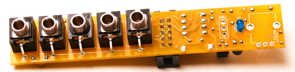
JACKS & LED
Now place the 3.5mm jacks into the PCB as shown below. Carefully turn over and solder in place. (Optional) You can place the panel on if you like before soldering to make sure that the jacks are aligned well.
Then insert the LED so that the SHORT LEAD is placed in the SQUARE Hole. This is very important as LEDs are polarized components. Turn over, solder and clip excess leads.
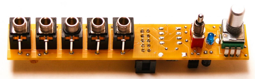
SWITCH & POTENTIOMETER
Add the potentiometer and switch into the PCB, then place the panel onto the project PRIOR to soldering them in place.
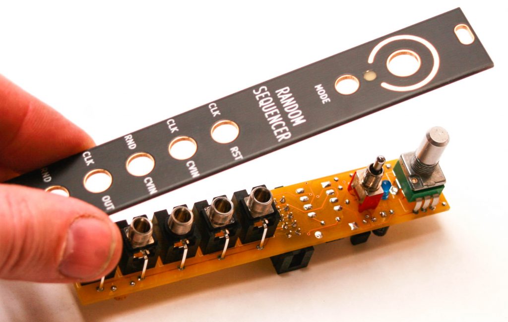
PANEL PLACEMENT
Carefully take the Eurorack panel and place it over the components. You can gently hand tighten the jack, switch and potentiometer nuts.
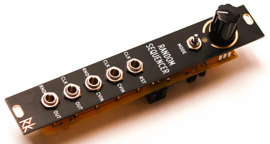
Turn the project over and solder the switch and potentiometer in place. THEN take the IC and place it in the socket by aligning the dot on the IC on the same size as the notch on the IC socket.
Cheers to you! You can now connect your 10 to 16 power cable and get ready to randomize!