Thank you for choosing Rat King Modular! We want to give you the best step-by-step instructions as possible to assist you in a successful build. Please make sure to follow these instructions in order and take your time! If you have limited experience please try and get some experience/help before attempting something that you are uncomfortable with. With that said, let’s begin!
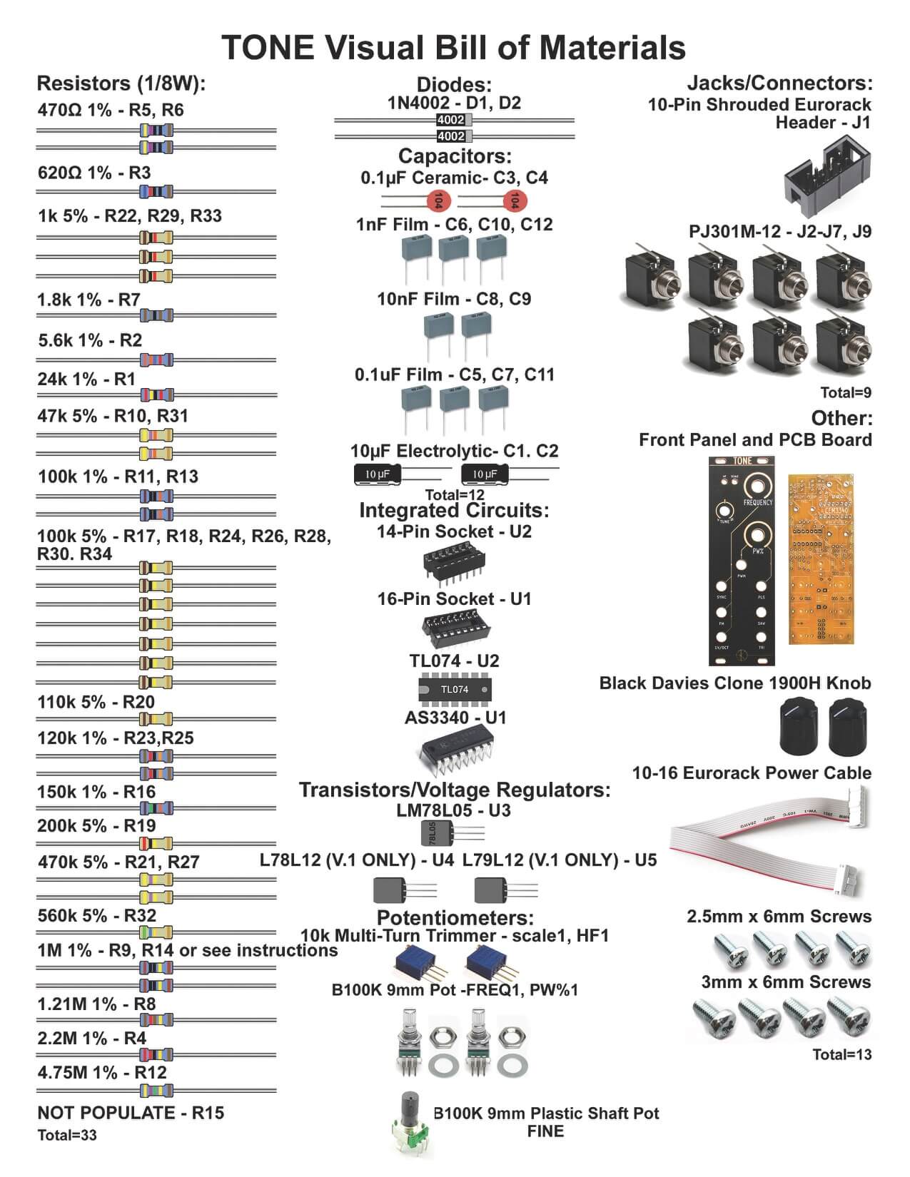
Here is a link to the bill of materials with Mouser part numbers.
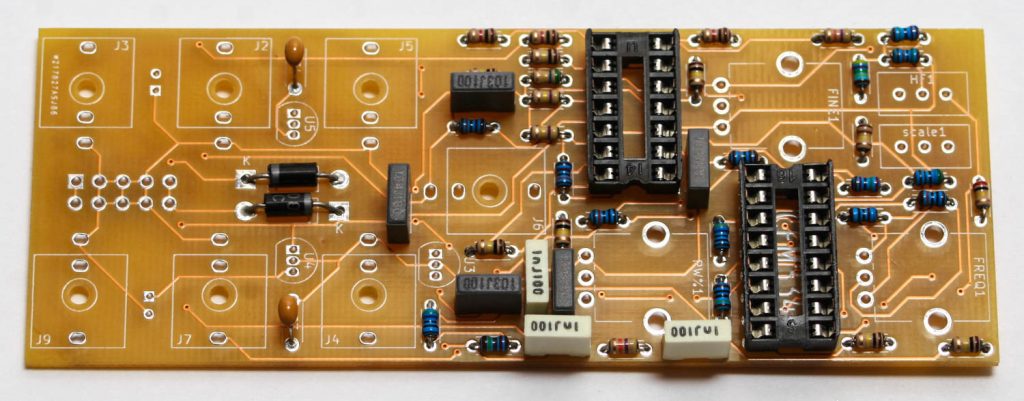
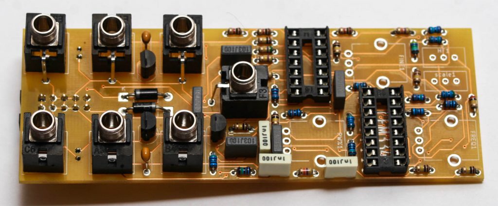
Resistors & Large Diodes
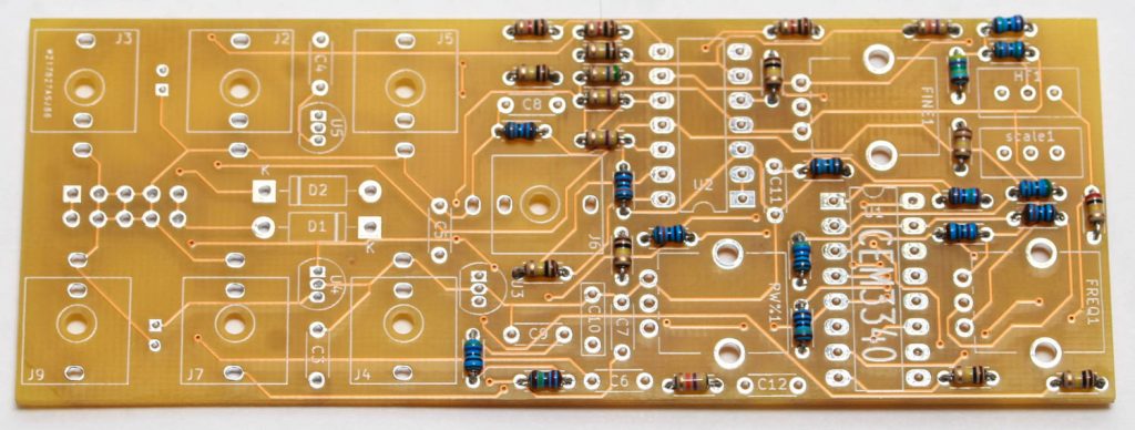
Up first are the resistors which are not polarized, so it doesn’t matter which way they are oriented. It makes troubleshooting a lot easier if you line up all of the tolerance bands (usually a gold stripe) on the same side. Insert each resistor, matching the value to the proper spot as per the BOM.
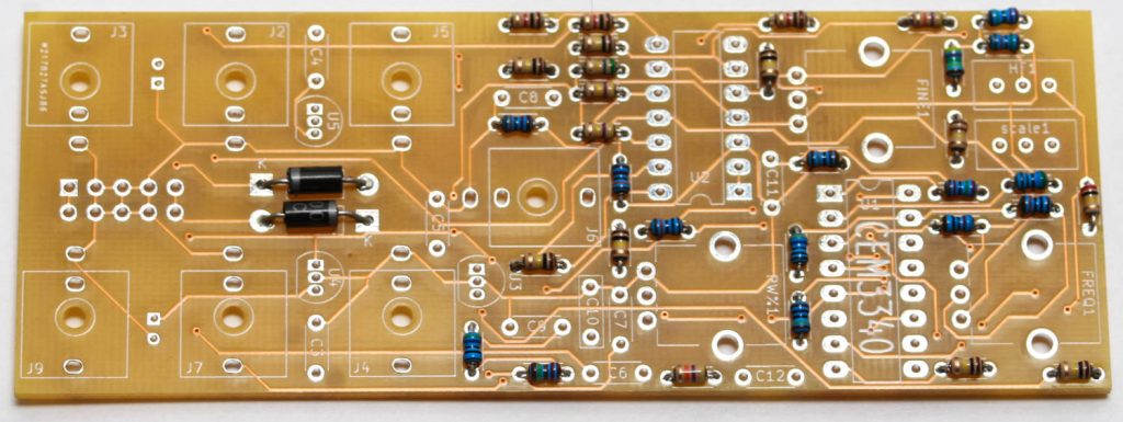
After that, you can put the 4002 diodes, which are polarized, so make sure that you match up the silver stripe on the diode with the stripe on the silk screen.
IC Sockets
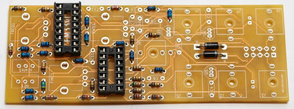
Place the IC sockets and make sure that you align the notch in the IC socket with the notch in the PCB silk screen. Don’t solder just yet!
V.2 Disregard these instructions and populate R14 normally:
V.1 ONLY: Take one of the 1M Ohm resistors and place it between pins 4 and 5 on IC U1 and carefully solder it in. You can now solder the rest of the IC Socket pins
Ceramic & Film Capacitors
Populate the ceramic and film capacitors next. These capacitors are not polarized so they can be inserted in either direction.
Transistors & Voltage Regulator
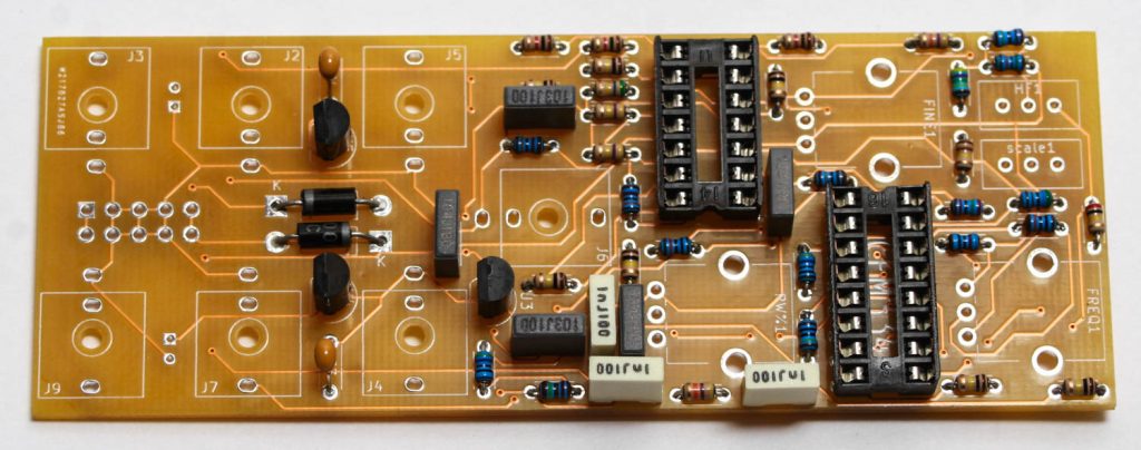
V.2 The +12V and -12V regulators have been removed from the project. Disregard.
V.1 Insert the +12V and -12V regulators
Next populate the transistors and voltage regulator by aligning the flat part of the transistor with the flat side of the silk screen. Turn over and CAREFULLY solder in place. The pad spacing for the transistors is very close together. Be careful to not use too much solder, you might bridge the pads!
Electrolytic Capacitors and Power Connector
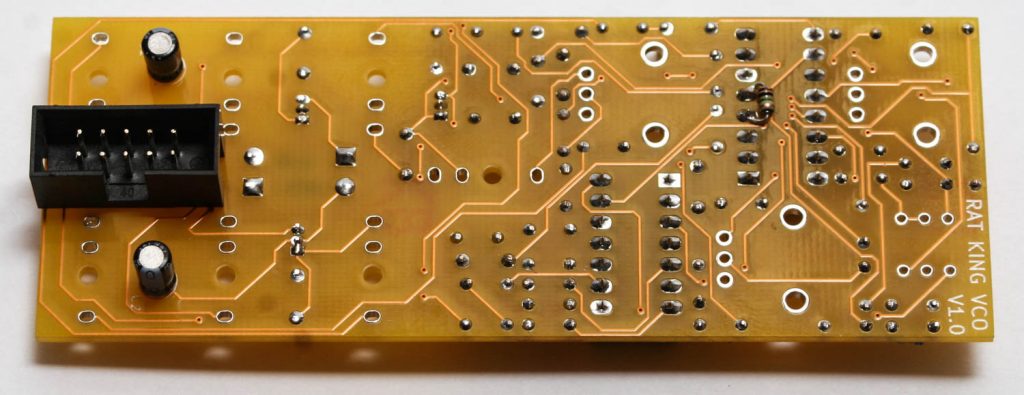
First populate the electrolytic capacitors. Electrolytic capacitors are polarized, so make sure when you are placing it that you orient the striped (negative) side of the cap toward the white half moon on the silk screen. Once inserted, turn your project over, solder and clip any excess leads.
Next populate the 10-Pin Eurorack power header as shown below. The header’s keyed notch aligns with the silk screen notch. This is very important, please do this correctly.
Jacks
Now place the 3.5mm jacks into the PCB as shown below. Carefully turn over and solder in place.
Timmer Potentiometers
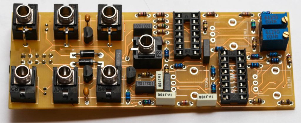
Now place the two multi-turn potentiometers in place as shown above. Make sure you do this exactly as shown the photo so that the trim screw will land behind the panel. Turn over, solder and carefully trim excess leads.
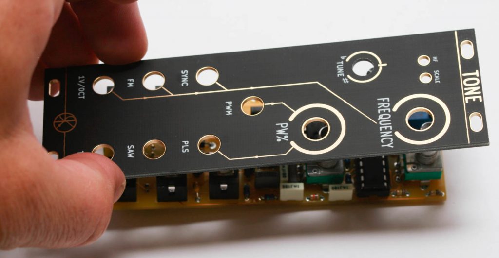
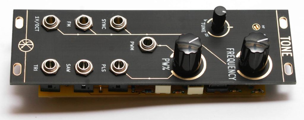
Potentiometers & ICs
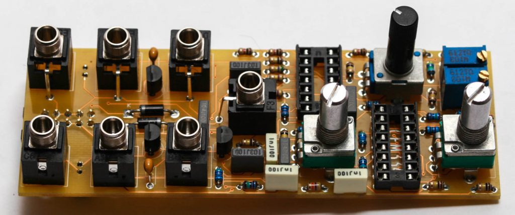
Add the potentiometers into the PCB, then place the panel onto the project PRIOR to soldering them in place.
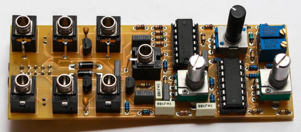
Now add the ICs by aligning the notch with the notch in the PCB silkscreen.
After you place the panel on and solder the pots in place, add the jack nuts and pot nuts.
You are now ready to test and calibrate your new VCO!
Calibration
1V/O Trimmer
- On the front of the panel (using the FREQUENCY and TUNE controls), tune to a fundamental frequency that can be easily verified several octaves up (e.g. 20Hz, 50Hz or 100 Hz).
- Apply 1V to the V/oct input.
- Adjust the SCALE trimmer to 2x the initial frequency.
- Apply 0V to the V/oct input.
- Readjust the FREQUENCY/TUNE pots the front panel to match initial frequency.
- Repeat steps 1-5 until 1V is 2x the original frequency.
- Repeat steps 1-6 until the first 6-8 octaves are calibrated, or you’re satisfied with the range that is calibrated.
HF Trimmer
This should only affect tracking at high frequencies, where there can be a slight drop in current within the exponential generator inside of the 3340 IC.
- Calibrate the V/oct trimmer first.
- On the front of the panel (using coarse and fine controls), tune to a very high frequency (e.g. 2kHz, 4kHz, 8kHz).
- Apply 1V to the V/oct input.
- Adjust trimmer to 2x the initial frequency.
- Apply 0V to the V/oct input.
- Readjust the FREQUENCY/TUNE pots the front panel to match initial HIGH frequency.
- Repeat steps 3-6 until that octave is calibrated.
- Repeat steps 3-7 for each successive octave until satisfied.