Thank you for choosing Rat King Modular! We want to give you the best step-by-step instructions as possible to assist you in a successful build. Please make sure to follow these instructions in order, and take your time! If you have limited experience, please try and get some experience/help before attempting something that you are uncomfortable with. With that said, let’s begin!
Here is a link to the bill of materials with Mouser part numbers.
Here is a visual bill of materials:
Resistors & Small Diodes
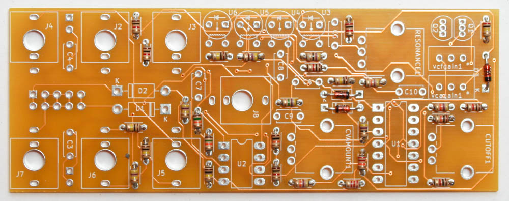
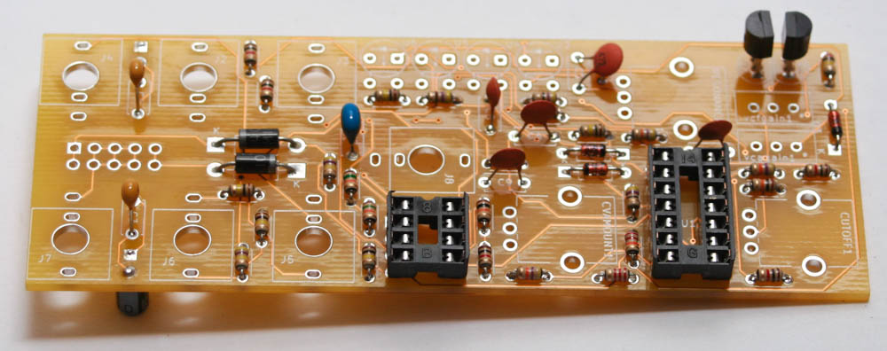
Up first are the resistors, which are not polarized, so it doesn’t matter which way they are oriented. It makes troubleshooting a lot easier if you line up all of the tolerance bands (usually a gold stripe) on the same side. Insert each resistor, matching the value to the proper spot as per the BOM. Next place the small diodes in, which are polarized, so match up the line on the diode with the line on the PCB silk screen.
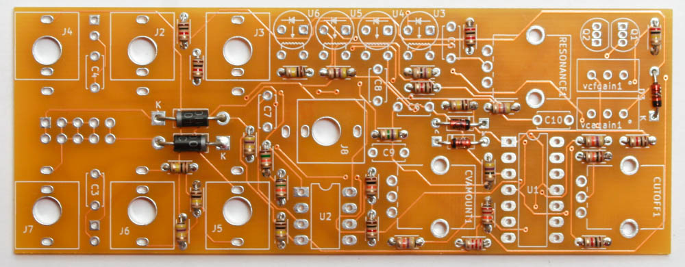
After that, you can put the larger diodes, which are polarized, so make sure that you match up the silver stripe on the diode with the stripe on the silk screen.
IC Sockets
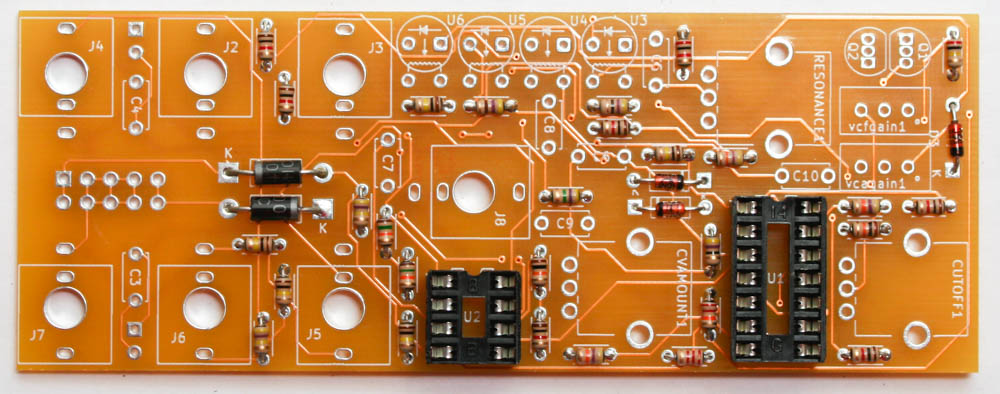
Place the IC sockets and make sure that you align the notch in the IC socket with the notch in the PCB silk screen. Turn the PCB over and solder them in place.
Ceramic Capacitors
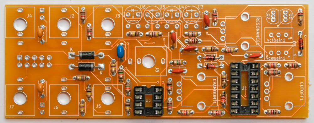
Populate the ceramic capacitors next. These capacitors are not polarized, so they can be inserted in either direction.
Transistors & Voltage Regulator
Next populate the transistors by aligning the flat part of the transistor with the flat side of the silk screen. Turn over and CAREFULLY solder in place. The pad spacing for the transistors is very close together. Be careful to not use too much solder, you might bridge the pads!
Vactrols
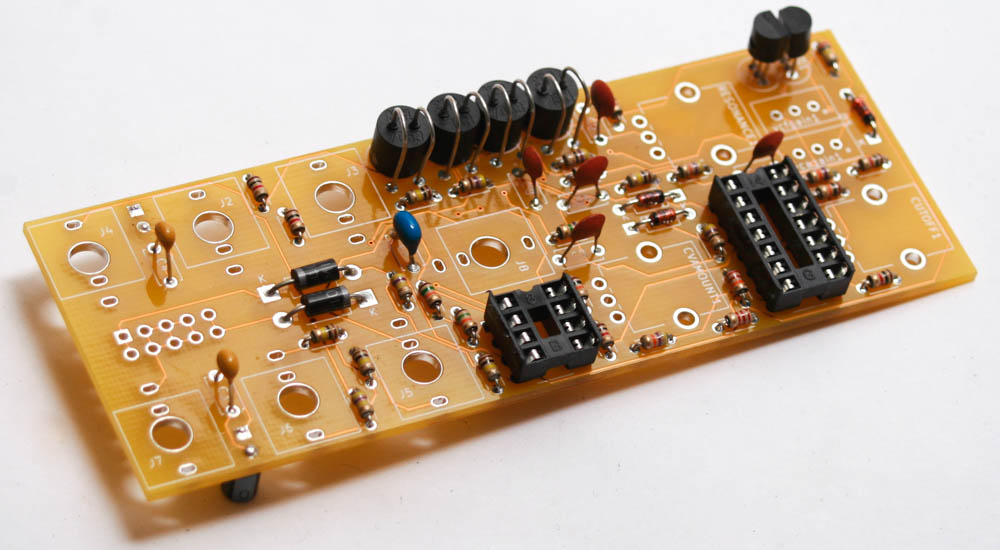
Insert the four Vactrols in the PCB as shown above by matching the white dot on the Vactrols (shorter leads) with the cathode on the Silk screen PCB graphic (on the side toward the jacks). The longer leads are for the variable resistance so bend those smooth and insert in the other side. Solder in place on the reverse side.
Electrolytic Capacitors and Power Connector
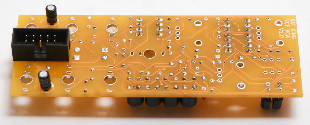
First populate the electrolytic capacitors. Electrolytic capacitors are polarized, so make sure when you are placing it that you orient the striped (negative) side of the cap toward the white half moon on the silk screen. Once inserted, turn your project over, solder and clip any excess leads.
Next populate the 10-Pin Eurorack power header as shown below. The header’s keyed notch aligns with the silk screen notch. This is very important, please do this correctly.
Jacks
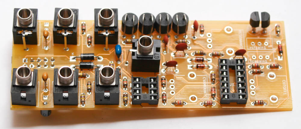
Now place the 3.5mm jacks into the PCB as shown below. Carefully turn over and solder in place.
Pots and ICs
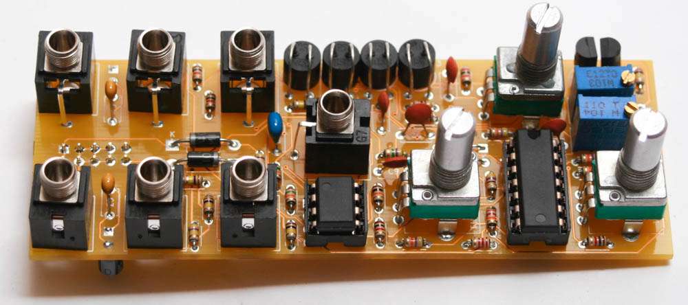
Now place the two multi-turn potentiometers in place as shown above. Make sure you do this exactly as shown the photo so that the trim screw will land behind the panel. Turn over, solder and carefully trim excess leads.
Add the potentiometers into the PCB; do not solder them in yet.
Now add the ICs by aligning the notch with the notch in the PCB silkscreen.
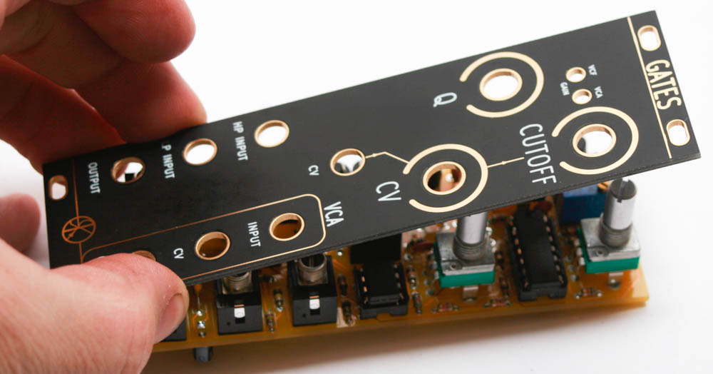
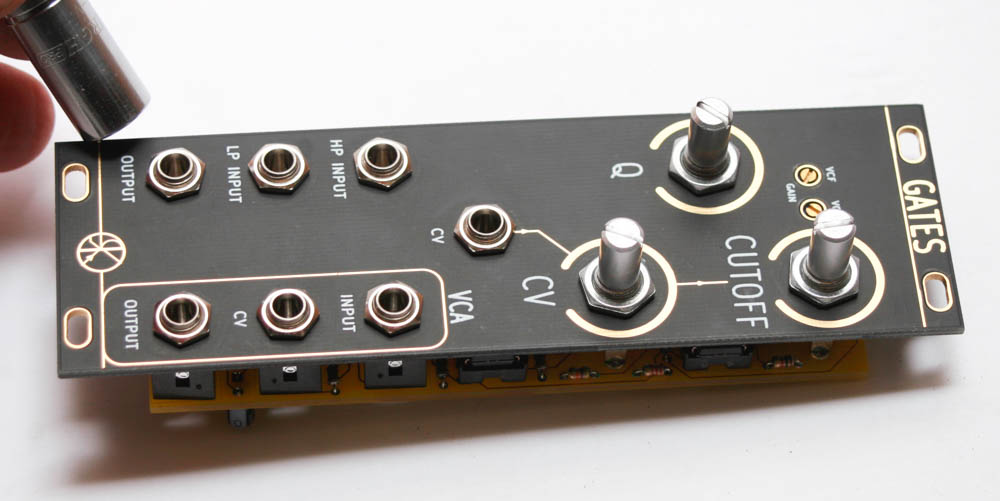
After you place the panel on and solder the pots in place, add the jack nuts and pot nuts.
You are now ready to test and calibrate your GATES module
Calibration
VCF Trimmer
- Mult your input signal (sine wave recommended) and connect one signal to channel 1 of your oscilloscope.
- Take one of the other multed signals and patch it into the LP INPUT. Turn the CUTOFF knob fully CW.
- Patch the left-hand OUTPUT jack to channel 2 of your scope.
- Turn the VCF trim pot so that channel 1’s amplitude is as close as possible to matching the GATES OUTPUT amplitude (it may be slightly different).
VCA Trimmer
- Mult your input signal (sine wave recommended) and connect one signal to channel 1 of your oscilloscope.
- Take one of the other multed signals and patch it into the VCA INPUT.
- Patch 5V into the VCA CV jack (the CV jack below the INPUT jack).
- Patch the VCA OUTPUT jack to channel 2 of your scope.
- Turn the VCA trim pot so that channel 1’s amplitude is as close as possible to matching the GATES OUTPUT amplitude (it may be slightly different).