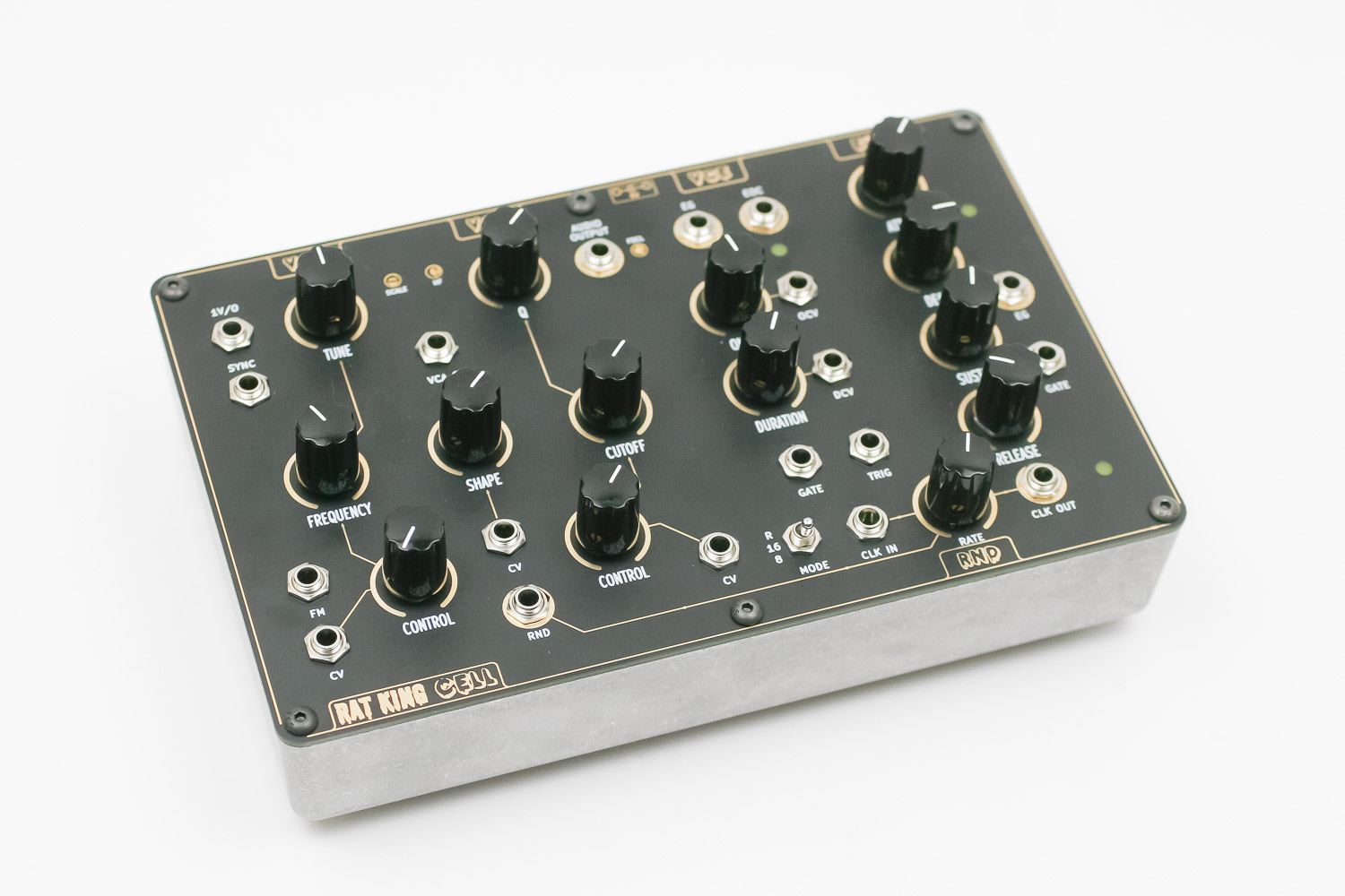
These instructions cover both the Console and the Eurorack version.

Click here to view a bill of materials with Mouser part numbers.
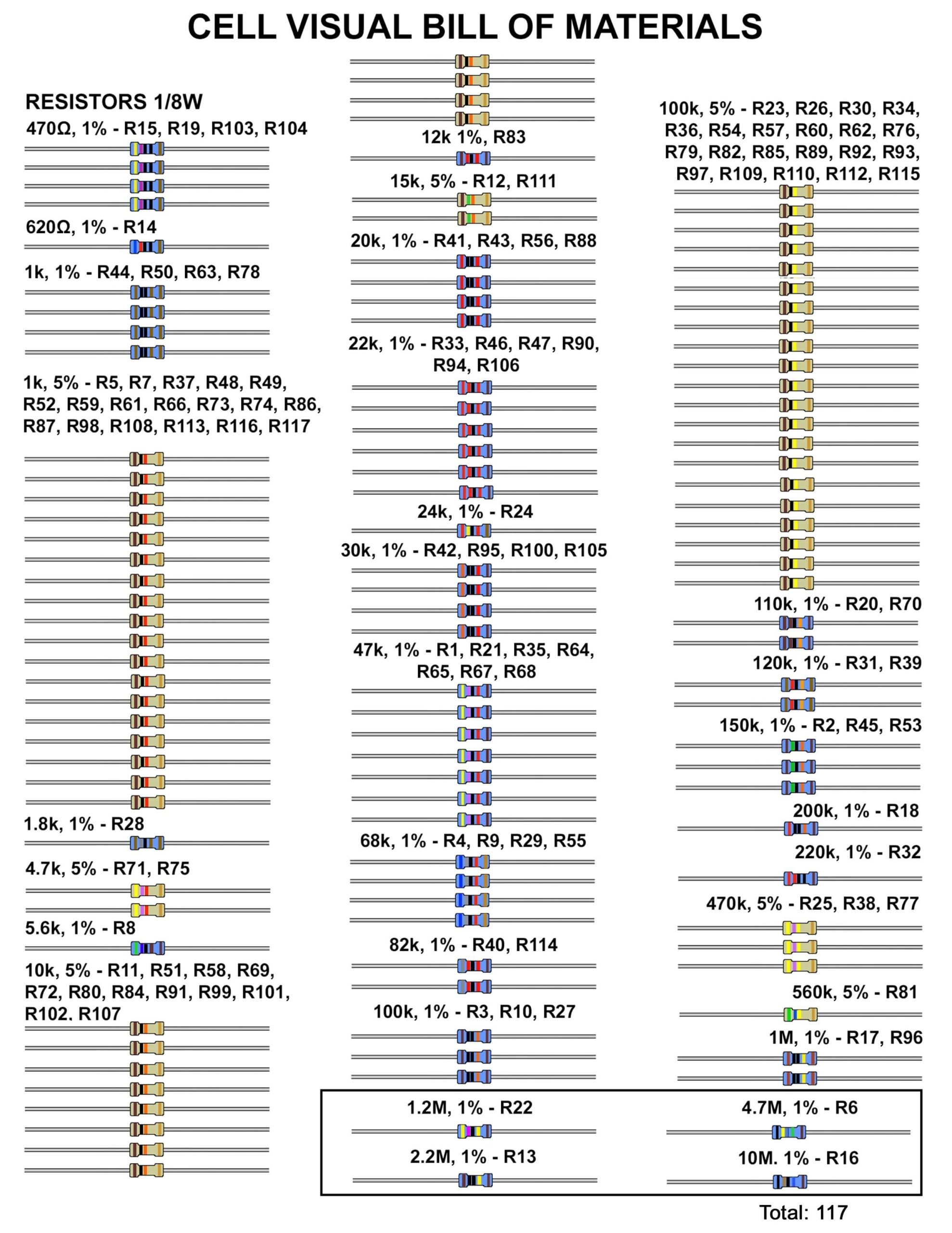
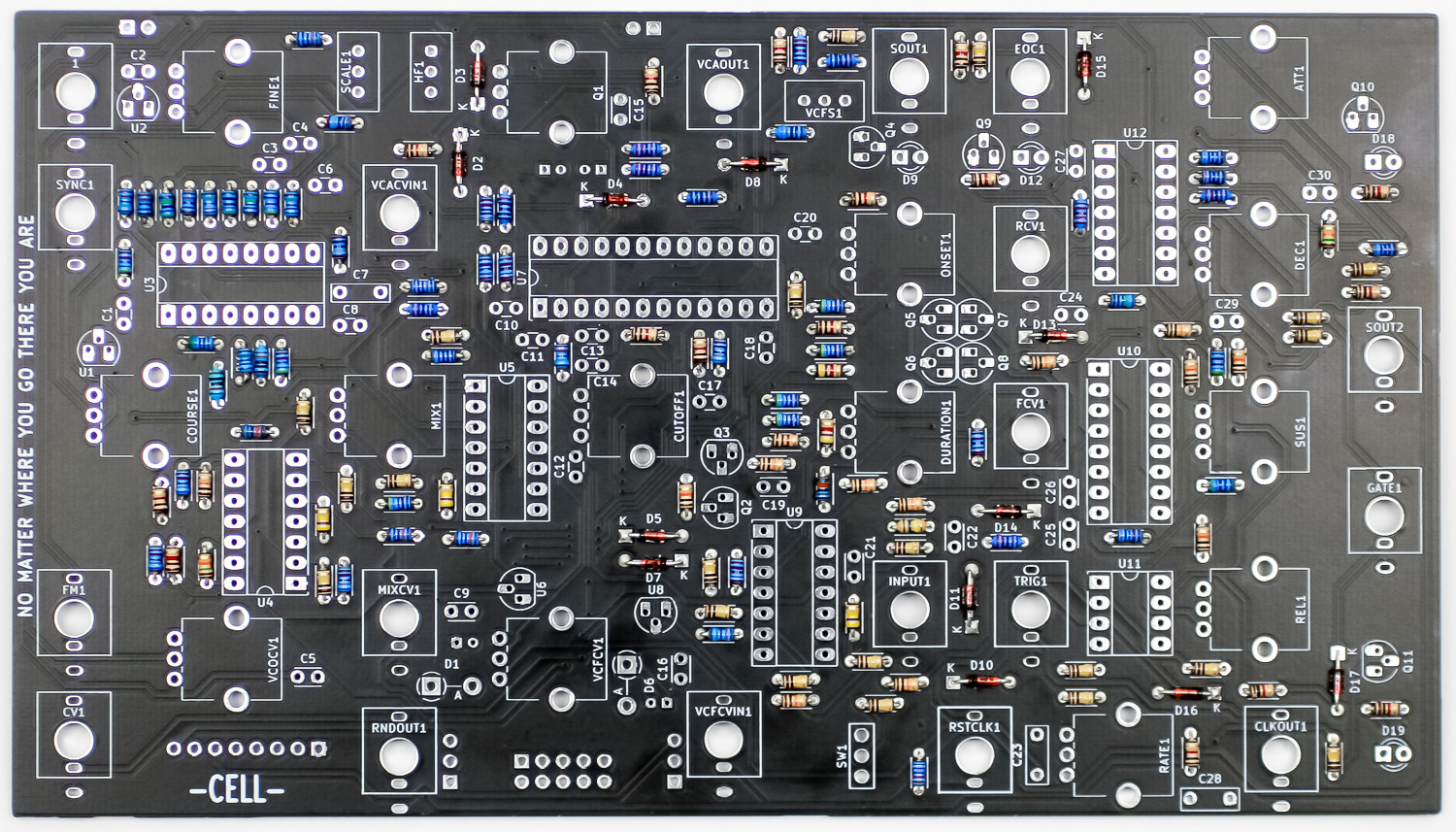
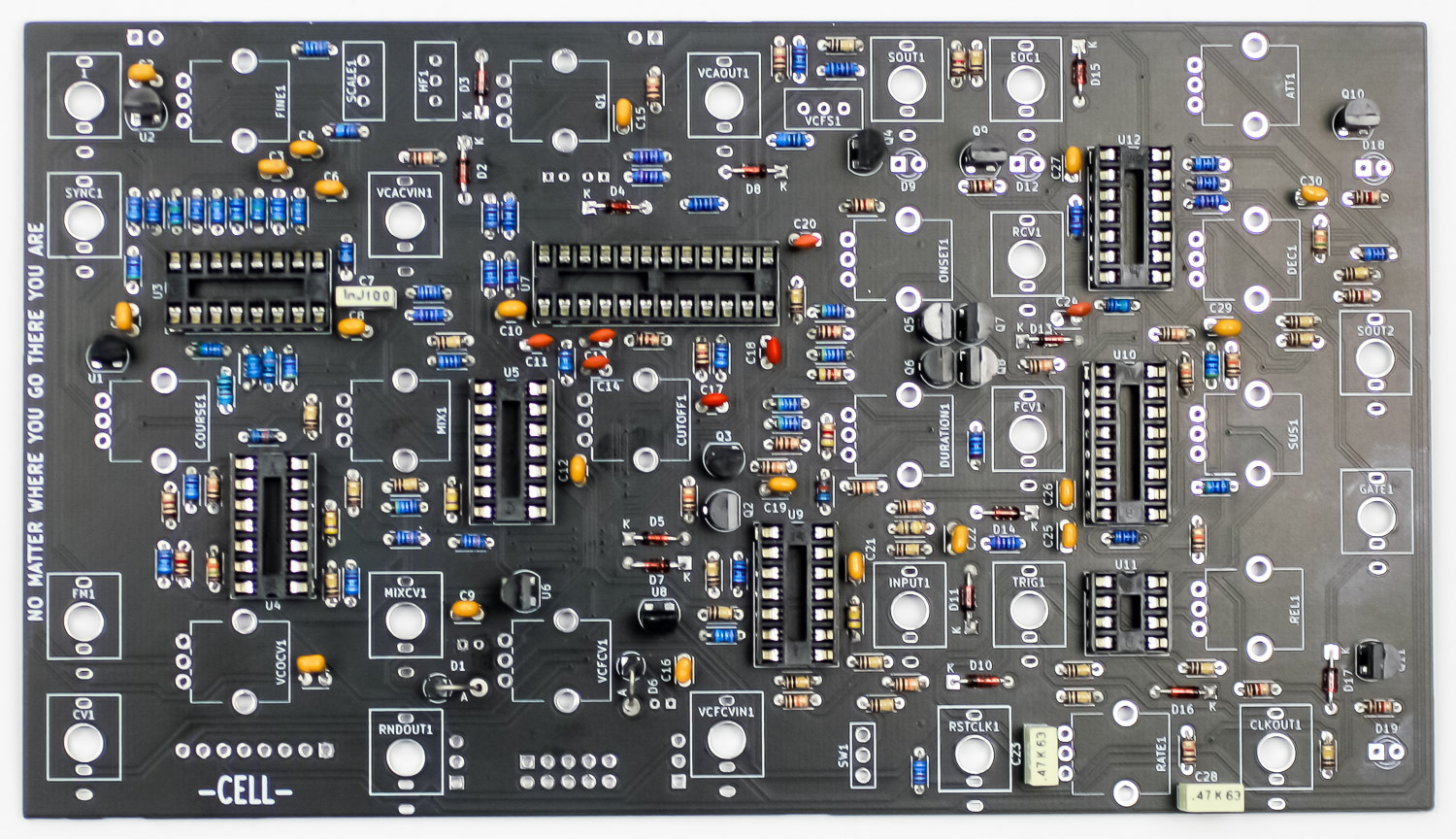
RESISTORS
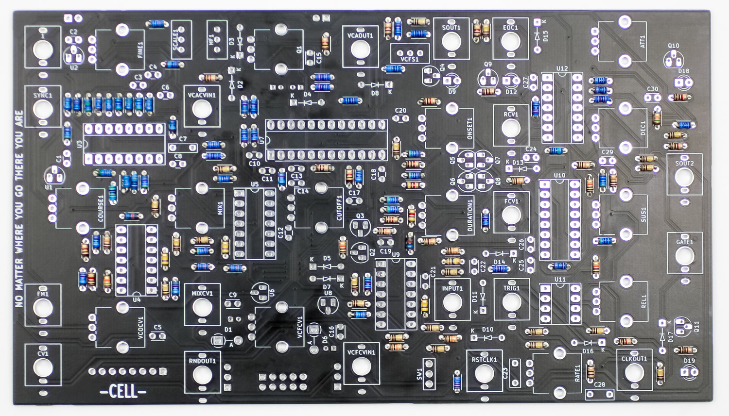
Follow the BOM and place all of the 1/8W resistors in the PCB as shown below. Carefully turn the project over and solder the resistors in place. Clip excess leads.
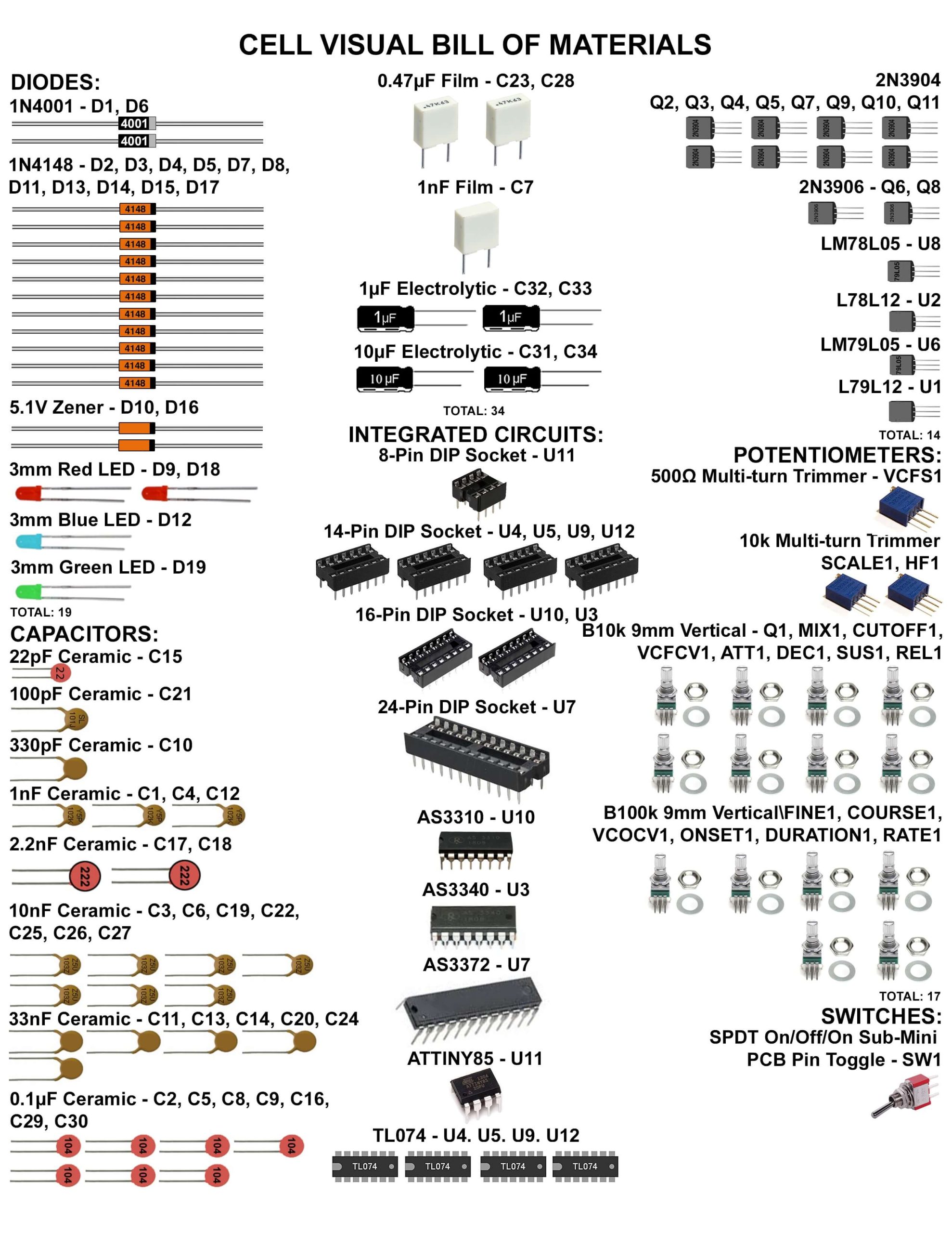
DIODES
Now align the diodes by matching the stripe on the PCB with the stripe on the diode and place them into the PCB. Don’t populate the 1N4001 diodes yet. Turn over to solder then clip excess leads.
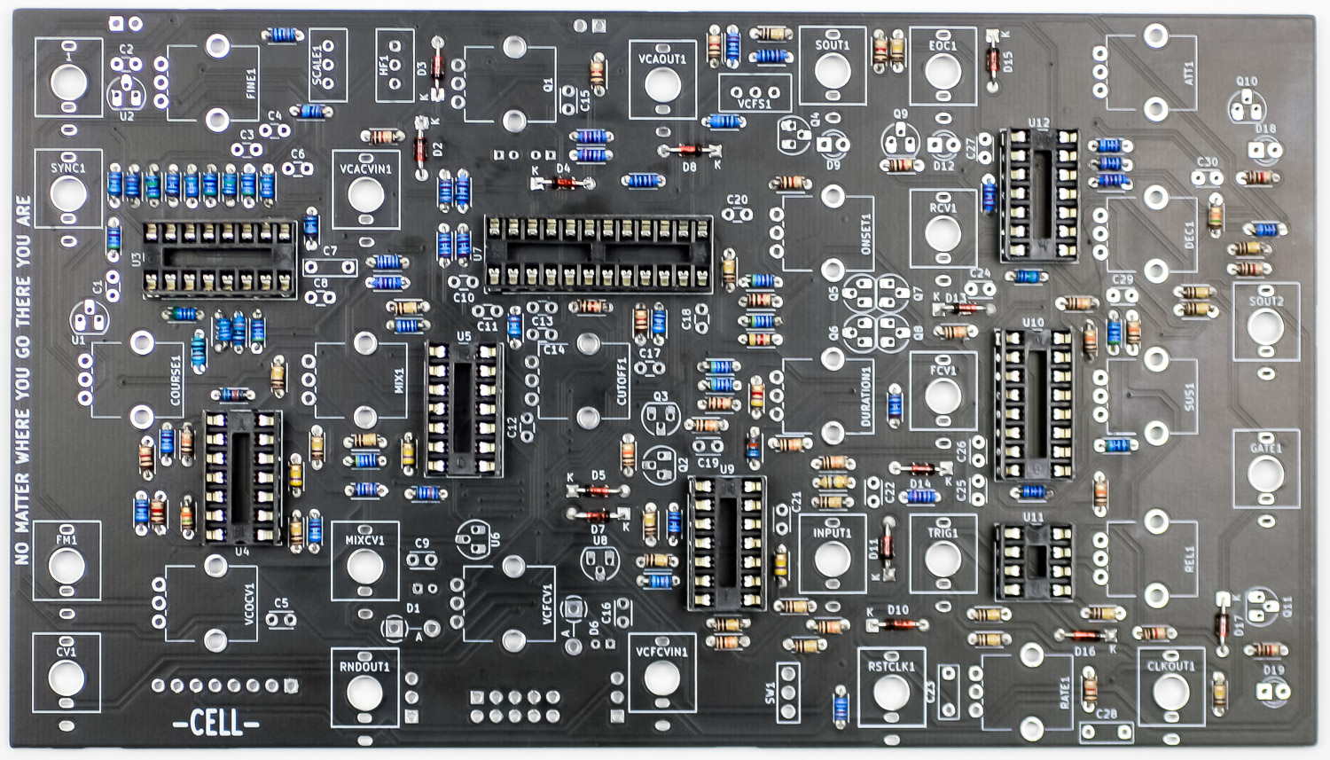
IC SOCKETS
Place the IC sockets into the PCB as shown below by aligning the notch on the IC socket with the notch on the PCB silkscreen. Turn over to solder in place.
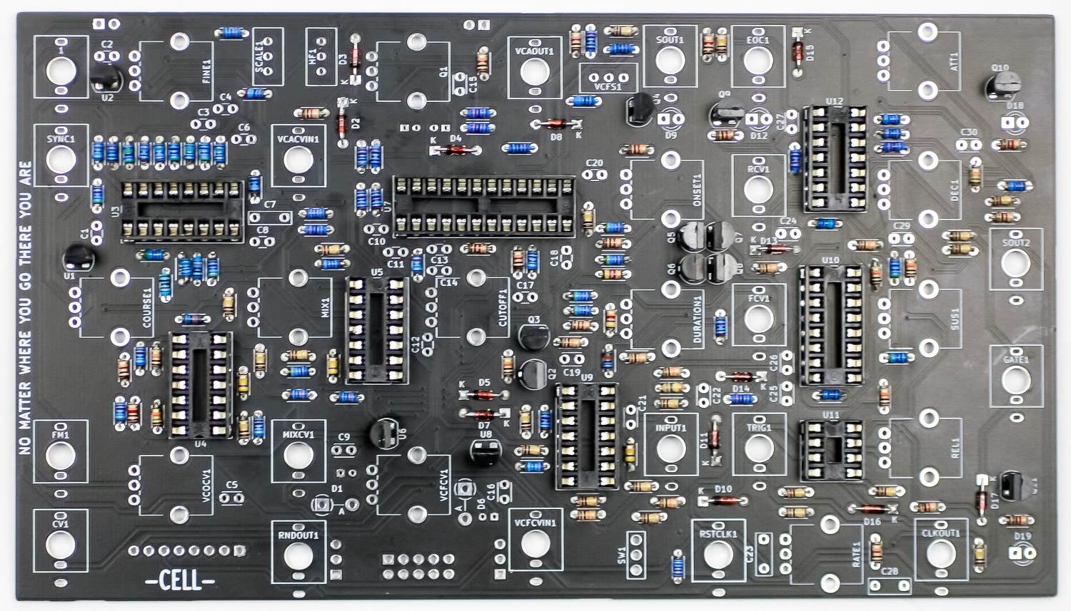
TRANSISTORS
Populate all of the transistors into the PCB by aligning the flat side of the transistor with the flat side of the PCB silkscreen. Turnover to solder in place then clip excess leads.
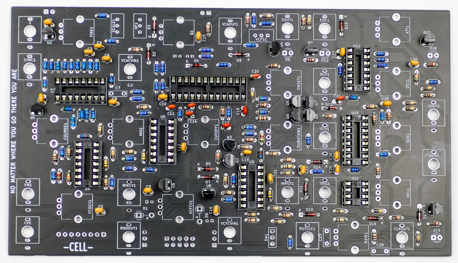
CERAMIC CAPACITORS
Populate all of the ceramic caps as shown below then turn over to solder in place then clip excess leads.
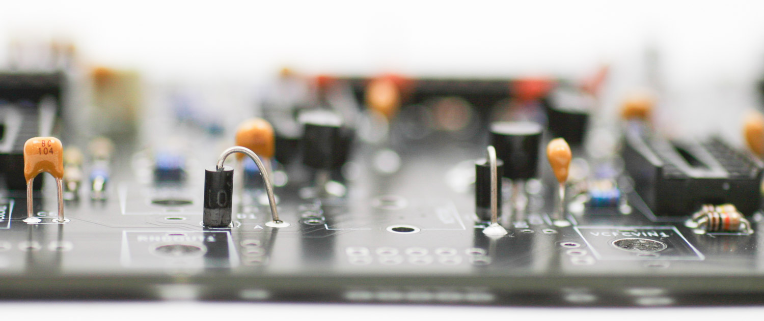
REMAINING CAPS & BENT DIODES
Place the remaining caps into the PCB, solder and clip. Place in the two standup 1N4001 diodes, solder and clip.
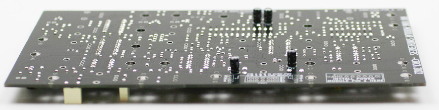
ELECTROLYTIC CAPS
Turn the PCB over and then populate the electrolytic caps into the PCB as shown below. Make sure that you orient the caps properly. Solder in place and then clip lead excess.
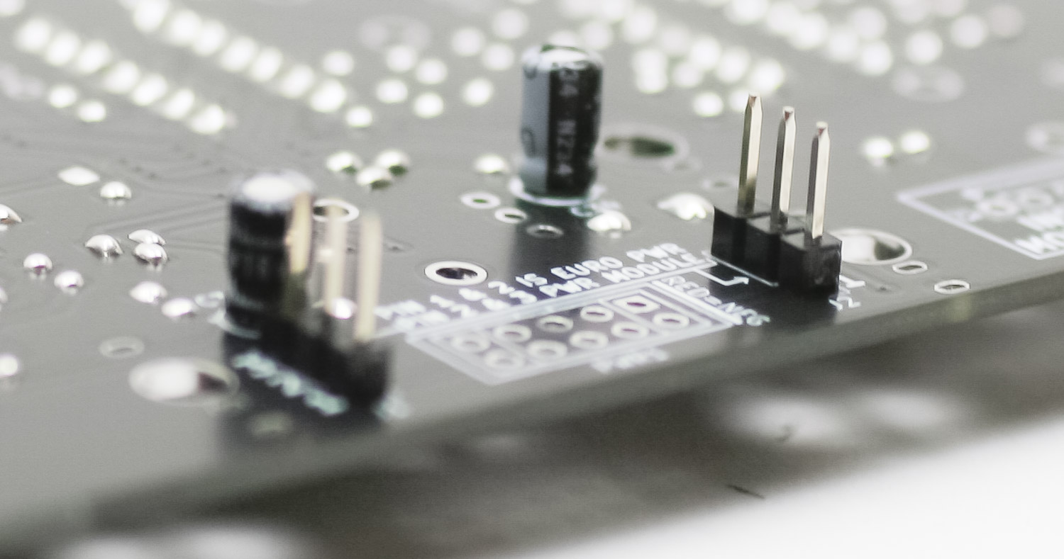
HEADER PINS
Place the two 3-pin header pins into the PCB. Solder in place.
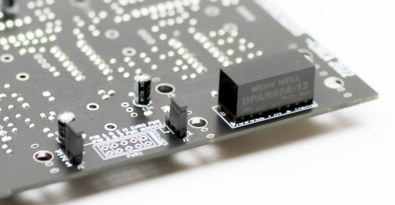
POWER CONVERTER – CONSOLE VERSION ONLY
Solder the power converter into the PCB as shown below. You can also place the 3 pin jumpers in place.
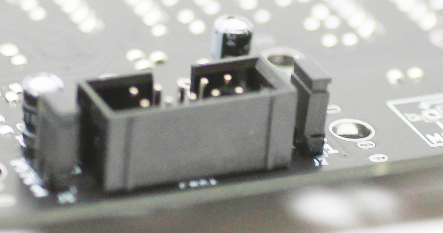
10-PIN POWER HEADER – EURORACK VERSION ONLY
Solder the 10-pin power header in place as shown below.
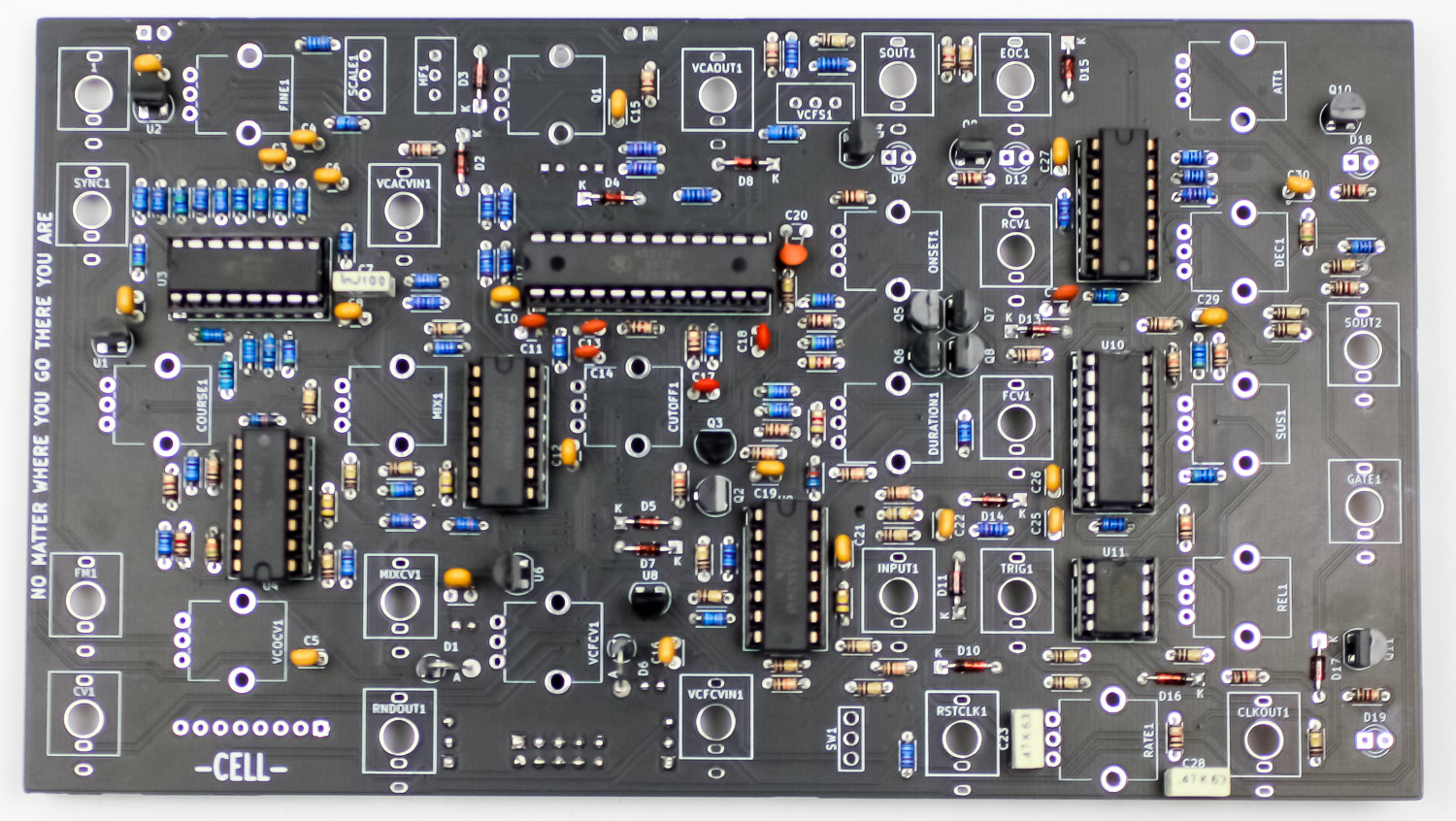
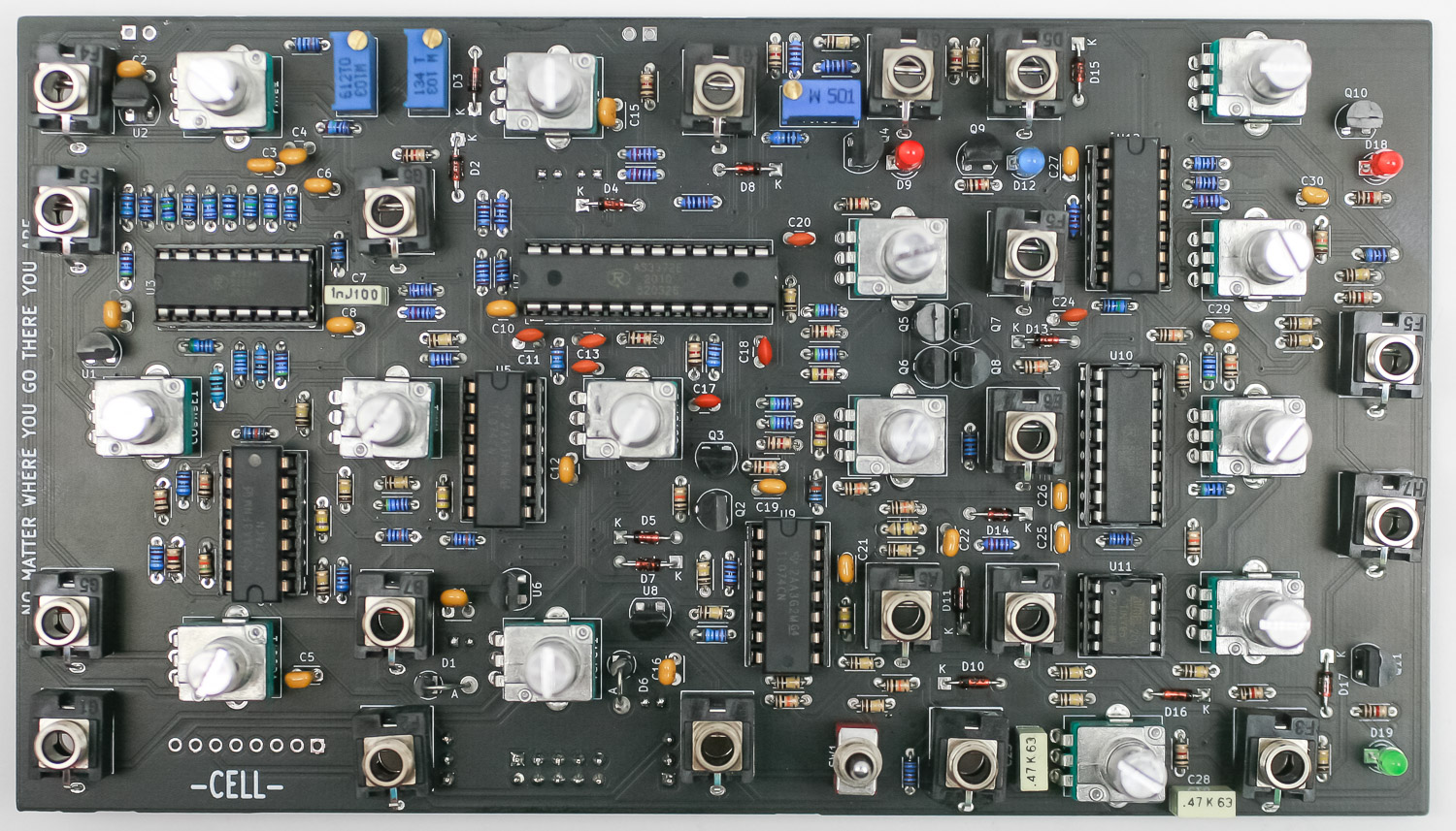
IC PLACEMENT
Place all the ICs into the project as shown below. Align the notch on the IC with the notch on the socket.
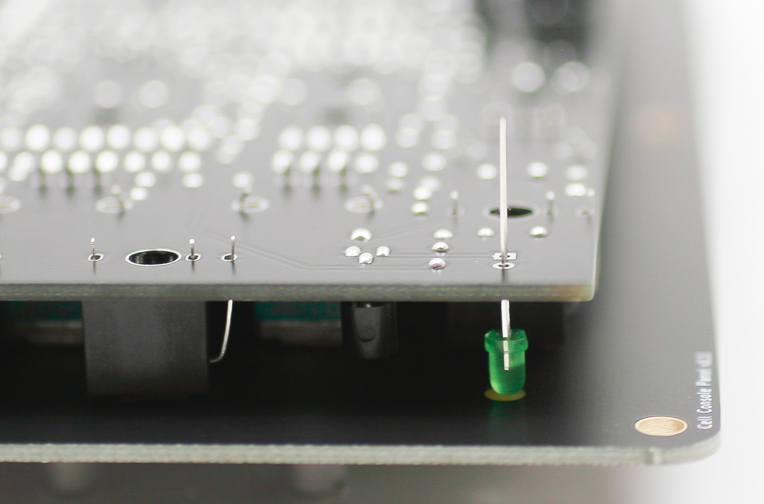
POTS, JACKS, SWITCH, LEDs
Populate all of the jacks, pots, switch, and LEDs. Polarize the LEDs properly. Wait until the panel is placed over these items to solder.
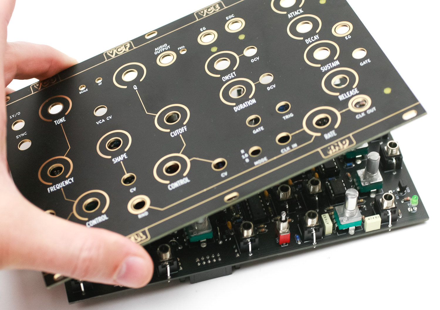
Gently tighten down the pot, jack and switch nuts. Be careful with your project at this point as nothing is soldered just yet.
Next, push the LED up to the panel. You can now solder the jacks, pots, switch and LEDs in place.
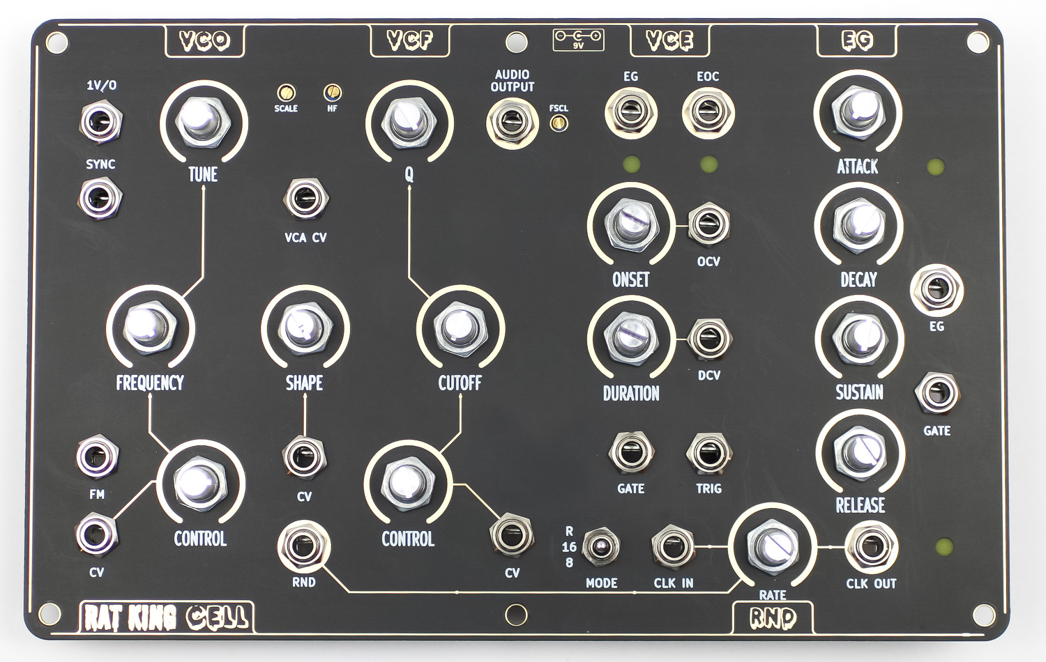
EURORACK FINISHED
If you are building the Eurorack version of the CELL, you are done and ready to test your module.
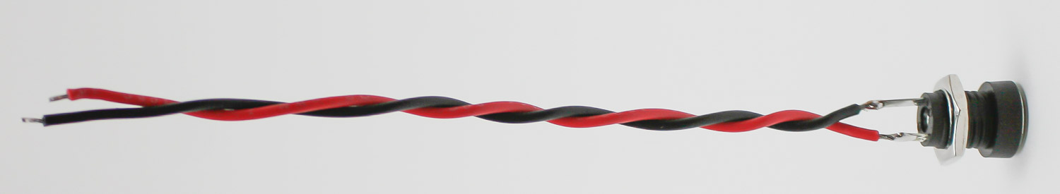
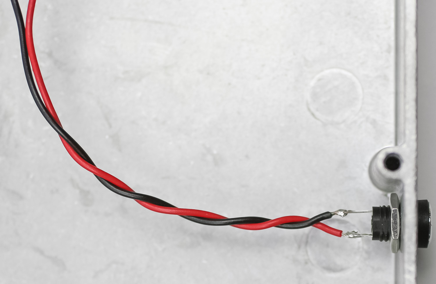
DC JACK – CONSOLE VERSION ONLY
Solder the wire to the DC jack as shown below by soldering the black wire to the longer lead on the DC jack.
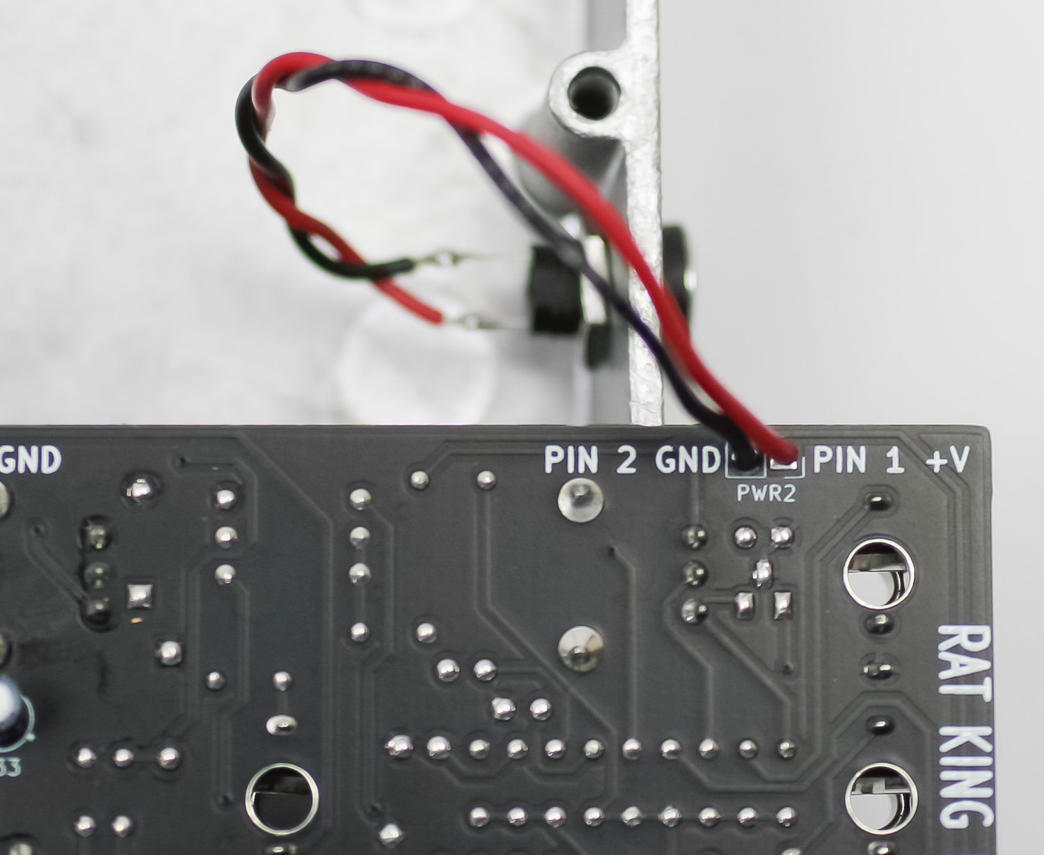
Solder the DC jack wires to the PCB as shown below
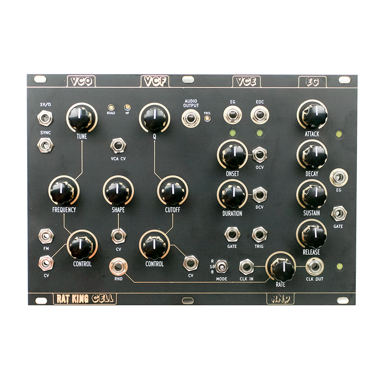
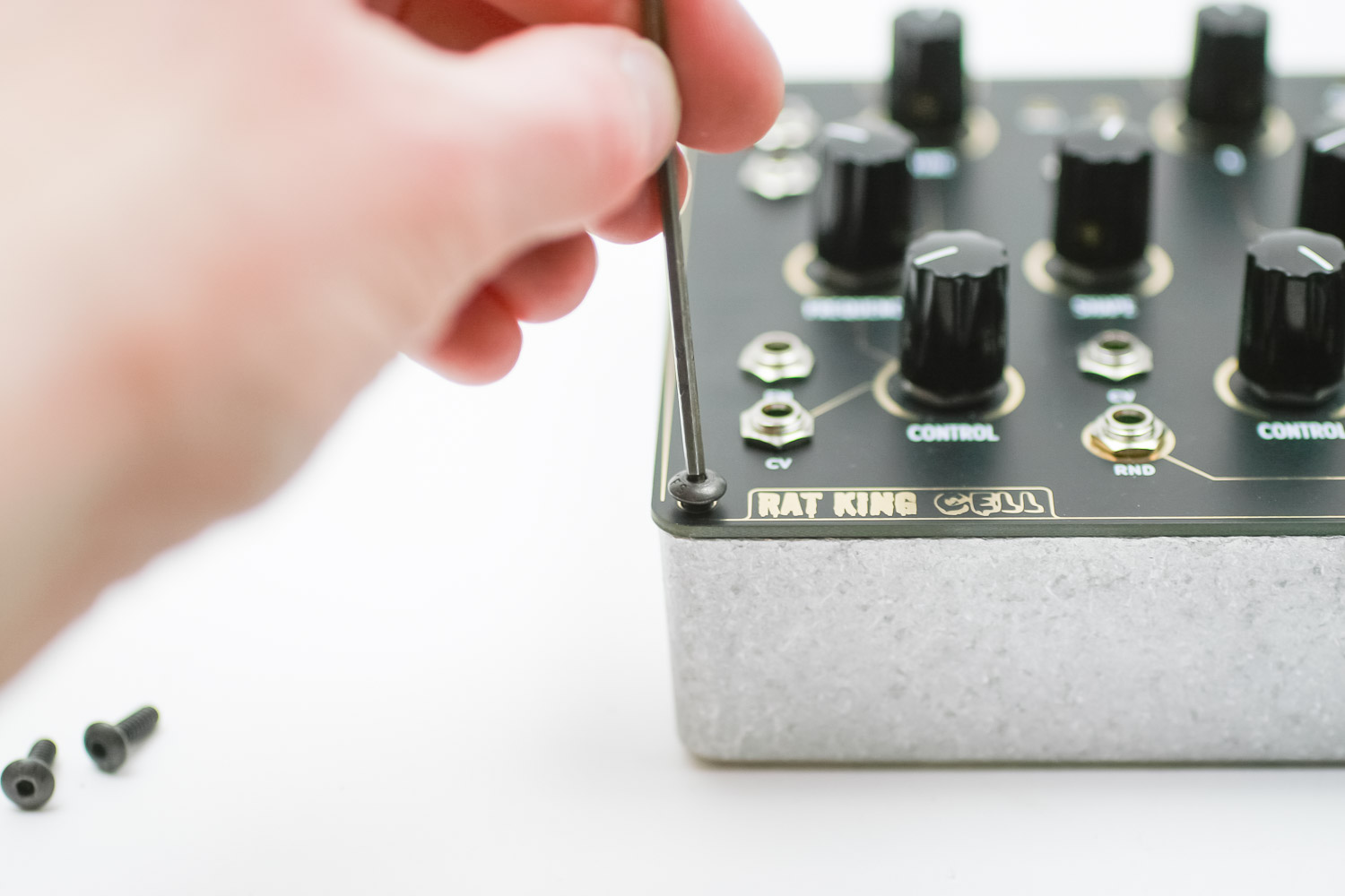
CASE PLACEMENT – CONSOLE VERSION ONLY
Place your project into the included case, screw it down (using a 2mm or 5/64″ Allen/hex key) and get ready for testing!
CONGRATS!